Introduction
In this exercise, we will simulate a simple cantilevered beam with a fixed end and a load applied to the other end. Here is the basic process:
- Open the model of the beam in Autodesk Inventor.
- Apply a property, constraints, and a load.
- Mesh and run the simulation.
- Review the displacement and stress results, and compare to the expected result.
These are the assumptions we will use for this simulation:
- The displacement is small.
- The material exhibits a linear stress-strain response.
- The applied load does not change in magnitude, orientation, or distribution.
- The effects of gravity are negligible.
1. Open the Model
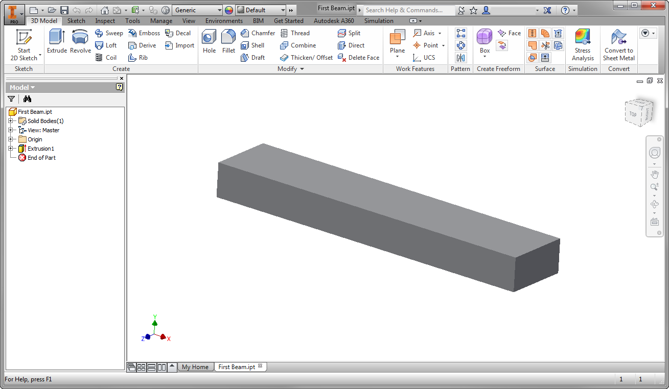
Start Autodesk® Inventor, and open First Beam.ipt from the Section 3 - Cantilevered Beam sub-folder of your training exercises folder. You should see this:
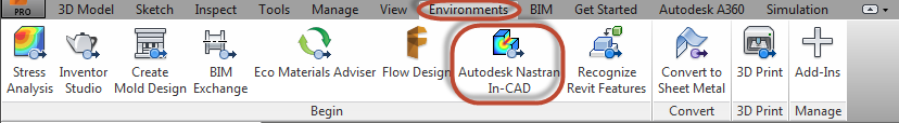
2. Start the Autodesk® Nastran® In-CAD Environment
- From the ribbon, click the Environments tab.
- Click Autodesk Nastran In-CAD.
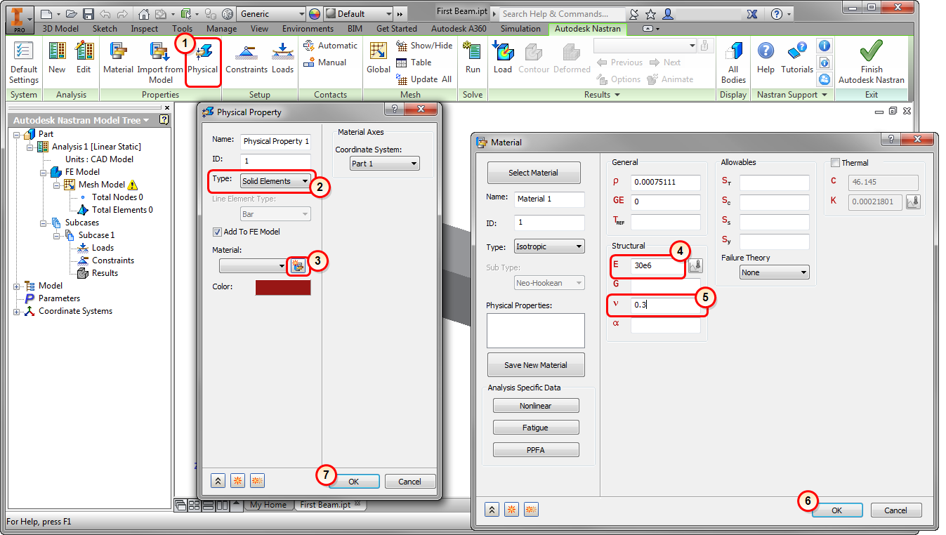
3. Assign the Physical Property
- Click Physical from the ribbon.
- On the Physical Property dialog, confirm the Type is Solid Elements.
- Click the Material icon.
- On the Material dialog, enter 30e6 for E (Young's Modulus).
- Enter 0.3 for v (Poisson Ratio).
- Click OK on the Material dialog.
- Click OK on the Physical Property dialog.
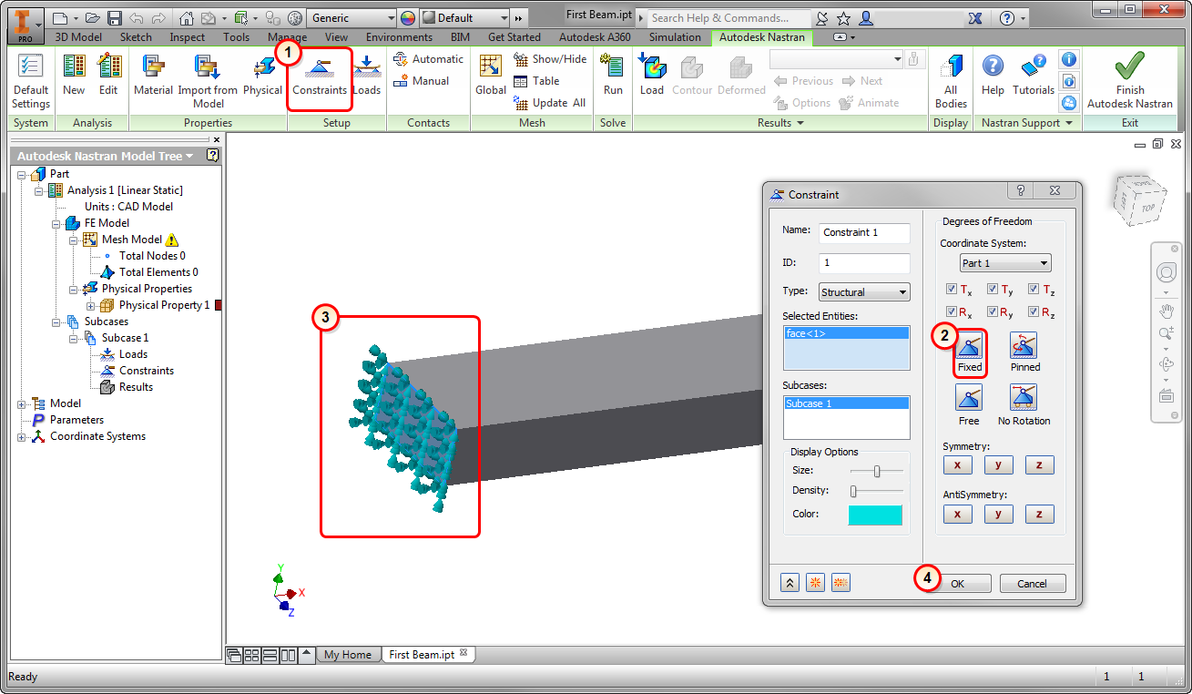
4. Constrain the Beam
In this step, we assign the condition that fixes the beam on one end, preventing movement in any direction.
- Click Constraints from the ribbon.
- On the Constraint dialog, click Fixed. (This is the default setting.)
- Click the end of the beam, as shown in the image.
- Click OK.
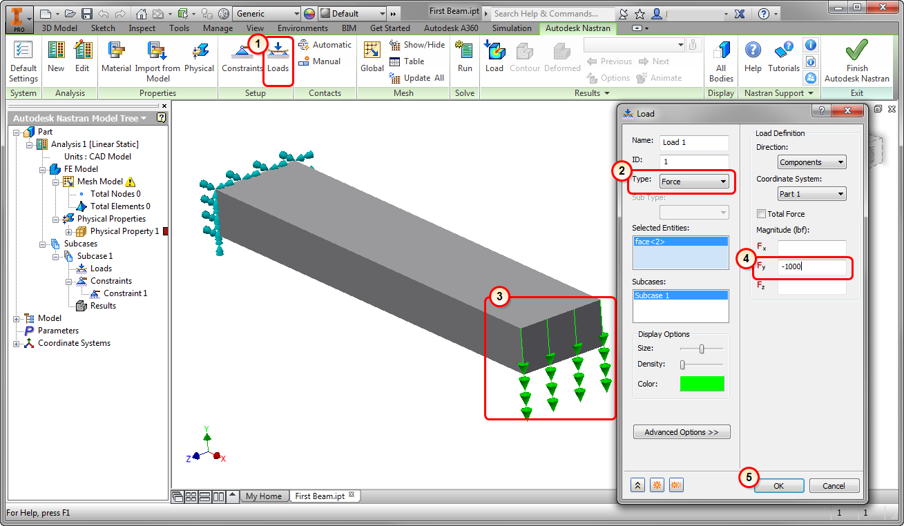
5. Load the Beam
- Click Loads from the ribbon.
- Note that Force is the default Type of load.
- Select the end of the beam that does not have the constraint (as shown).
- Enter -1000 for Fy.
- Click OK.
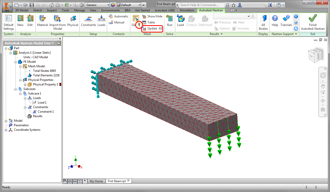
6. Mesh the Beam
- Click Update All from the ribbon.
The mesh generates:
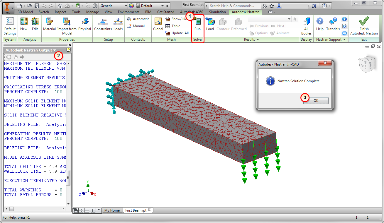
7. Run the Simulation
- Click Run from the ribbon.
- The Tree automatically switches to the Autodesk Nastran output. This is a log of the solution progress.
- When the solution is complete, click OK.
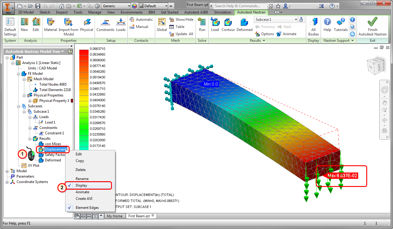
8. Visualize Displacement
- Right-click on Displacement from the Model Tree.
- Select Display.
Note the maximum displacement of 0.066 inches.
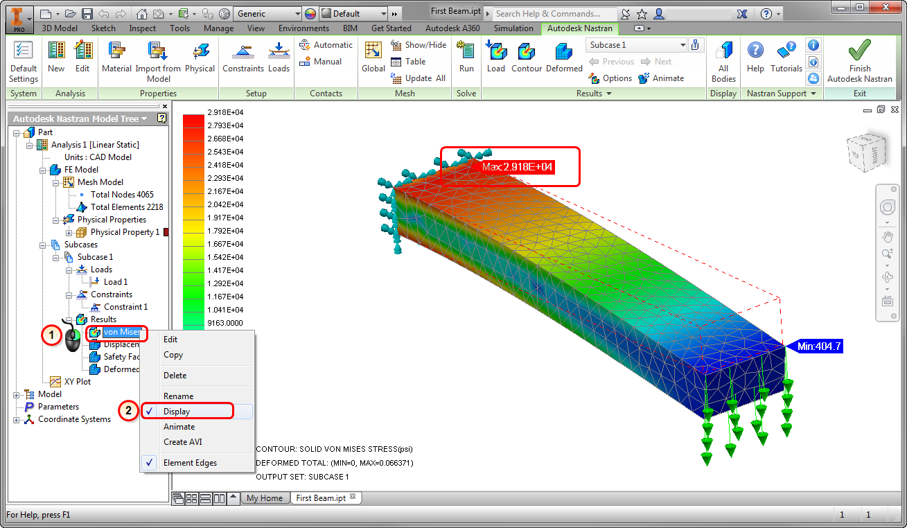
9. Visualize Stress
- Right-click on von Mises from the Model Tree.
- Select Display.
Note the maximum stress of 29,000 psi.
Summary
Congratulations! You have finished your first FEA model in Autodesk® Nastran® In-CAD!
When we compute the response by hand, we find the following:
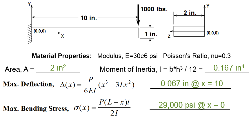
|
Previous Topic: The Basics of Finite Element Analysis (FEA) |
Next Topic: The User Interface |