We now create a joint between the piston and the connecting rod. The joint allows the parts to rotate relative to each other about the centerline of the hole.
- Click
 View
View Navigate Orientation Right View.
 - Use
 View Navigate Zoom Window to zoom in on the area where the piston and connecting rod meet.
 - Press Esc to terminate the Zoom Window tool.
- Click
 Selection Shape Circle to change to the circle selection method.
 - With the
 Selection Select Surfaces option active, draw a circle enclosing the hole where the piston and connecting rod meet, as shown in the following image.
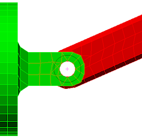
- Click
 Mesh CAD Additions Joint. The Joint Mesh Setup dialog box appears. The three selected surfaces (two holes in the piston and one in the connecting rod) are listed under the Participating surfaces heading. The joint type is shown as the default Pin Joint (lines to axis endpoints). The Part number has been automatically set to 4, the next available unused part number. Note: It is also possible to add surfaces to the Participating surfaces list by selecting them and clicking Add after starting the Create Joint command.
- Activate the Do not dismiss dialog after joint generation option. You will add two more joints after this one. This option keeps the command active after you create a joint, for convenience.
- Click OK to add the pin joint. A new part appears in the browser, and the model appears as shown in the following image.
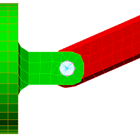
Note: The Part number has been incremented by one and the Participating surfaces list has been cleared in preparation for the next joint to be created.