Next, we will look at the displacement results with a transparent view of the undisplaced shape superimposed on the displaced view. Then, we will look at the rotational displacement and stress results.
- Select
 Results Contours
  Displacement Show Displaced Displaced Options
command.
Displacement Show Displaced Displaced Options
command.
- Click
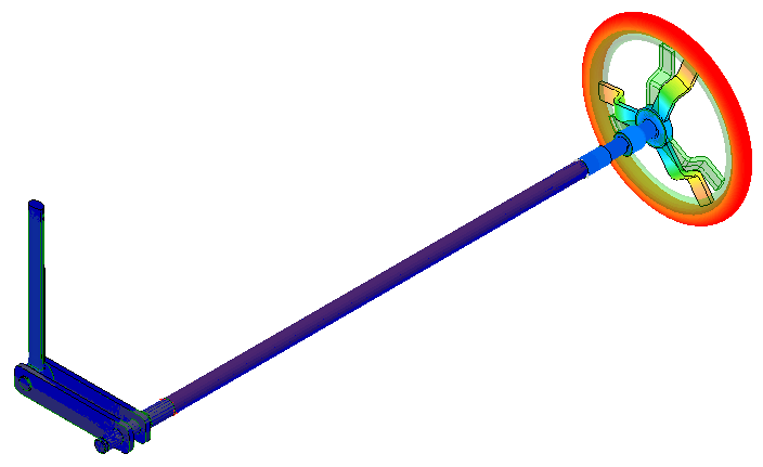
Transparent. The display appears as shown in the following image. Note that the displacement is almost purely torsional. That is, the hand wheel is rotating about its center.
- Click Do Not Show to remove the transparent overlay of the undisplaced shape.
- Close the Displaced Model Options dialog box.
- Click
Transparent. The display appears as shown in the following image. Note that the displacement is almost purely torsional. That is, the hand wheel is rotating about its center.
- Click
 Results Contours Displacement Rotation Magnitude. The
Rotation
command is in the pull-out portion of the
Displacement
panel. The
Magnitude
command is in the drop-down menu of the
Rotation
command. The rotation magnitude (twist) of the beam elements at the wheel end of the assembly is approximately 3 degrees.
Results Contours Displacement Rotation Magnitude. The
Rotation
command is in the pull-out portion of the
Displacement
panel. The
Magnitude
command is in the drop-down menu of the
Rotation
command. The rotation magnitude (twist) of the beam elements at the wheel end of the assembly is approximately 3 degrees.
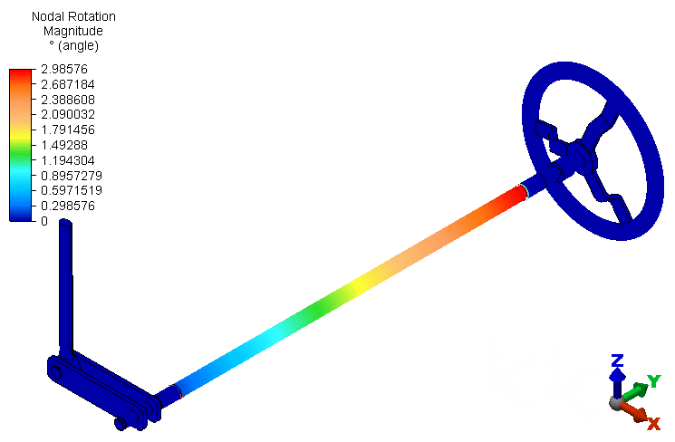 Note: Rotational displacement results are available for beam elements because beam elements support rotational degrees of freedom (DOF). However, only translation DOF, and therefore only translational displacement results, are available for brick elements. For this reason, all of the brick parts show a zero-rotation result.
Next, we look at the Von Mises stress results.
- Click
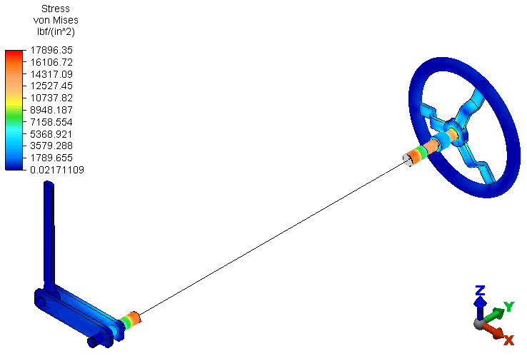
 Results Contours Stress von Mises. The model displays as shown in the following image. The highest stresses occur in the hand wheel shaft and the solid and hollow portions of the shaft spanning between the hand wheel and the remote crank subassemblies. Von Mises stress results are not applicable to the beam or rigid elements.
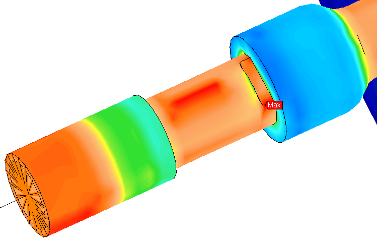
Here is a view with the model viewpoint rotated and zoomed in to clearly show the maximum stress region. Additionally, the Maximum Probe (
 Results Inquire Probes Maximum) has been turned on to indicate the maximum stress location.
Next, we look at the beam Worst stress results.
- Click
 Results Contours Stress Beam and Truss Worst. The following stress contour plot appears:
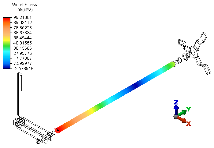 Important: The beam element formulation only calculates bending and axial stresses. Beam elements do not provide torsional stress results. The subject beam elements have no axial load and only a very small bending moment due to the reaction force at the partial link, which acts at a short distance from the shaft support. That is why the reported stress magnitude in the beam elements is so small. Use the preceding Von Mises results at the short brick-element portions of the hollow shaft (or the XY or YZ stress tensors) to account for the torsional stresses.Note: Though the beam elements do not produce torsional stress results, they do provide correct torsional displacement results. The element formulation includes the torsional resistance property, and therefore behaves with the correct torsional stiffness.
Finally, we look at the reaction force in the Z-direction at the end of the partial link (where it is constrained).
- Click
 Results Contours Reactions Reaction Force (Negative) Z.
- Click
 View Navigate Zoom Window.
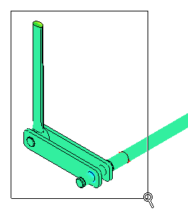
- Click and drag your mouse to draw a zoom area window enclosing only the partial link and crank, as shown in the following image:
- Press Esc to terminate the Zoom Window tool.
- Click and drag your mouse to draw a zoom area window enclosing only the partial link and crank, as shown in the following image:
- With the
 Selection Shape Point or Rectangle and
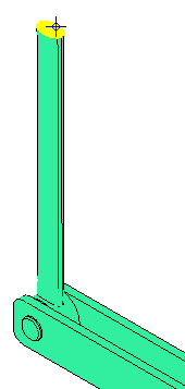
 Selection Select Surfaces commands active, click on the top surface of the partial link, as shown below (pre-highlighted in yellow):
- Right-click in the display area and choose
Select Related Nodes from the context menu. All of the nodes on the top surface of the partial link are now selected.
- Click
 Results Inquire Inquire Current Results. The Z-reaction results are listed for each of the selected nodes.
- In the Inquire: Results dialog box, choose the Sum option from the Summary drop-down selector.
Note: The sum of the nodal Z-reaction forces is 50.00 lbf. This is exactly the expected result, since a 200 in.lbf moment is applied to the hand wheel, the radius of the crank is 4 inches, and the partial link is at an angle of 90° relative to the crank (200 in.lbf / 4 in. = 50 lbf)
This tutorial is now complete.