ハードウェア レンダリング用のジオメトリ リマッピング

次の情報は、次の状況で発生する可能性があるジオメトリ データのリマッピングに焦点を当てています。
-
内部的に、または MFnMesh API インタフェースを通じてポリゴン メッシュが作成されてから
-
ハードウェア レンダリング用にジオメトリが提供されるまで
主な目的は、レンダリング時に提供される頂点データをどのようにオリジナルのジオメトリに再度マッピングできるかについて説明することです。特に、一連のオリジナルの四角フェースにデータをリマッピングすることが要件の場合を考慮しています。これは、Ptex テクスチャ マッピングなどの場合です。
まず、スムーズ メッシュ プレビュー(Smooth Mesh Preview)表示オプションに使用される基本三角形分割ロジックと均一サブディビジョン ロジックについて説明します。この情報は、カスタム リマッピングによって実行されるアルゴリズム(Maya が内部的に実行する方法と同様のアルゴリズム)を理解するために役立ちます。この情報は Maya 2016 のロジックに関するもので、VP1 (旧式の既定ビューポート) と VP2 (ビューポート 2.0)の両方に適用できます。
次に、シェーディング時のリマッピング データへのアクセスについて検討します。リマッピングされたデータを使用することの主な利点は、Maya の内部ロジック変更の複雑さにプラグインが対応する必要がないことです。提供されるデータには、頂点ごとの他のアトリビュート(位置や法線など)と同じ方法で、すべての内部データ操作が既に行われています。
この内部リマッピング ロジックは Maya 2016 の時点で最新のものですが、今後変更される可能性があります。このロジックのリバース エンジニアリングは推奨されていません。 また、三角形分割とスカルプトの実行、および適応型サブディビジョンに使用されるインデックス リマッピング ロジックは、VP2 の複雑さと非決定性を増します。
VP1 と VP2 両方のハードウェア シェーダ インタフェースの同等のリマッピング データへのアクセスについても検討します。
リマッピング ロジック
三角形分割
三角形分割は、ハードウェア レンダリング時に使用できるジオメトリ インデックスを生成するために行われます。三角形分割ロジックによって、分割にどのローカル頂点インデックスを使用するかが決定されます。どの分割が使用されるかについての知識が、三角形のペアのオリジナルの四角形へのマッピングを判断する際に役立ちます。
既定では、ポリゴン シェイプに使用されるロジックは最適シェイプの三角形の提供を試みます。しかし、リマッピングでは、どのように分割が行われるかについての予測可能性を得ることが最優先の目的です。そのためには、メッシュ シェイプの quadSplit アトリビュートを設定して予測可能性を向上させることができます。
quadSplit オプションは、四角形がどのように 2 つの三角形に分割されるかを決定します。左(Left)が選択されている場合は新しいエッジが 2 番目と 4 番目の頂点の間にでき、右(Right)の場合は 1 番目と 4 番目の頂点の間で分割します。最適シェイプ(Best Shape)は四角形のシェイプに基づいて最適な分割の選択を試みますが、これはアニメーション間でシェイプが変形するにつれて変化する可能性があります。
そのため、左(Left)または右(Right)の分割を選択したほうが予測可能性が向上します。
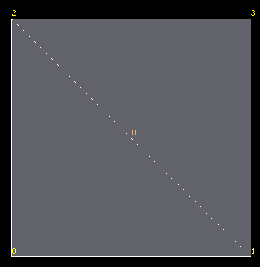
左(Left)の分割を以下のイメージに示します。分割が行われた箇所は点線で示しています。
それでも最適シェイプ(Best Shape)が必要な場合の四角形のリファレンス ロジックを以下に示します。一般的なアルゴリズムは穴がある可能性がある一般的な N 面ポリゴンを処理しますが、ここでは含まれていません。
v0 = quad vertex 0
v1 = quad vertex 1
v2 = quad vertex 2
v3 = quad vertex 3

dist02 = distance between v0 and v2
dist13 = distance between v1 and v3

// Use small tolerance so exact squares triangulate consistently
// one way rather than randomly due to rounding errors
fudgeFactor = 0.999f
canSplit = false
split02 = false

if( dist02 < fudgeFactor*dist13 )
{
    n1 = normal of triangle 1, 2, 0
    n2 = normal of triangle 2, 3, 0

    if( angle between n1 and n2 is less than 90 degrees )
    {
        if( area of triangle1 < 7 * area of triangle2 &&
                    area of triangle2 < 7 * area of triangle1 )
        {
            canSplit = true
            split02 = true
        }
    }
}
else
{
    n1 = normal of triangle 0, 1, 3
    n2 = normal of triangle 3, 1, 2

    if( angle between n1 and n2 is less than 90 degrees )
    {
        if( area of triangle1 < 7 * area of triangle2 &&
                area of triangle2 < 7 * area of triangle1 )
        {
            canSplit = true
            split02 = false
        }
    }
}

if( canSplit )
{
    if( split02 )
    {
        set triangle 1 = 1,2,0
        set triangle 2 = 0,2,3
    }
    else
    {
        set triangle 1 = 0,1,3
        set triangle 2 = 3,1,2
    }
}
else
{
   // Fall back to general triangulation algorithm
}サブディビジョン
ポリゴン シェイプのスムーズ メッシュ プレビュー(Smooth Mesh Preview)オプションは、オリジナルのジオメトリ データがリマッピングされる可能性があるもう一つの機会です。レンダリング時に提供されるジオメトリには、新しいジオメトリのセットを生成するために適用されたスムージング アルゴリズムがあるため、既存の頂点のインデックスを処理するためだけでなく、対応する新しいインデックスとともに導入される新しい頂点を処理するためにも追加のロジックが必要です。
次のセクションでは、OpenSubiv (OSD)または旧式の Catmull-Clark ロジックを使用する際の均一サブディビジョンのマッピング ロジック(ルール)について説明します。具体的には、頂点とフェースの巻上げ方向と新しい頂点のローカル パラメトリック(UV)位置について扱います。ローカル パラメータ設定は、テクスチャ マップ検索の必要性に応じてテクスチャ座標にリマッピングできます。
オリジナル ジオメトリはベース ジオメトリと呼びます。たとえば、オリジナル フェースはベース フェースです。
Maya の均一 OpenSubdiv サブディビジョン
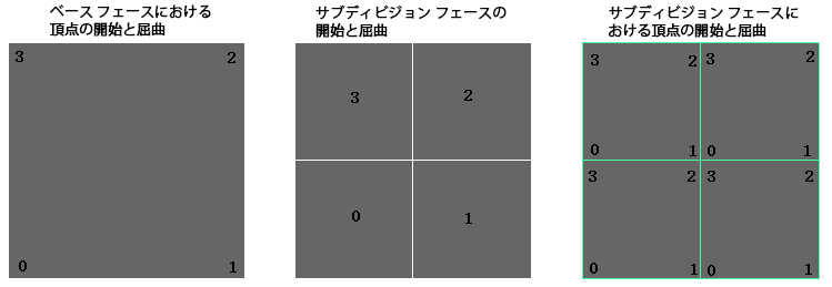
上の図は、ベース フェース(左のイメージ)と、1 レベルのサブディビジョンが適用されたときのサブディバイドされたフェースと頂点の開始点と巻上げ方向(中央と右のイメージ)を示しています。
ベース レベルに近いレベルが、高いと見なされます。サブディバイドされたフェースの順序は、このように高いレベルと一致して表示されます。開始フェースは、ベース フェースの開始頂点と揃った左下隅にあります。同様に、サブディバイドされたフェースの頂点も、左下隅から開始されます。巻上げ方向は常に反時計回りです。
ローカル UV の原点がベース フェースの頂点 0 にあると仮定すると、サブディバイドされたフェースにある頂点のローカル UV を推定できます。
ローカル パラメータ値を決定するためのサンプル コードを以下に示します。
// Get the UV of the bottom-left corner of the subdivided face.
//
// - subdFaceIndex, the index of subdivided face within a base face.
// - subdLevel, the Catmull-Clark subdivision level
//
// such that:
//
// - subdLevel >= 1
// - 0 <= subdFaceIndex <= 4^subdLevel
// - the UV value is encoded as an integer within [0, 2^subdLevel].
//
getSubFaceUV(subdFaceIndex, subdLevel)
{
    uv = (0,0);

    count = pow(4, subdLevel - 1);
    ofs = pow(2, subdLevel - 1);

    // Iteratively find the index of a parent face in each subdivision level,
    // and offset the UV accordingly.
    faceIndex = subdFaceIndex;
    while (count > 0) {
        start = faceIndex / count;
        switch (start) {
            case 0:                  break;
            case 1: uv += (ofs,0);   break;
            case 2: uv += (ofs,ofs); break;
            case 3: uv += (0,ofs);   break;
        }

        faceIndex %= count;
        ofs >>= 1;
        count >>= 2;
    }
    return uv;
}

// Get the UV of the vertex on the subdivided face.
//
// - subdFaceStartUV: the UV of the bottom-left corner of the subd face.
// - subdVertexIndex: vertex index on the subdivided face, 0~3.
//
getSubVertexUV(subdFaceStartUV, subdVertexIndex) {
    uv = (0,0);
    switch (subdVertexIndex) {
        case 0:              break;
        case 1: uv += (1,0); break;
        case 2: uv += (1,1); break;
        case 3: uv += (0,1); break;
    }
    return subdFaceStartUV + uv;
}

subdFaceStartUV = getSubFaceUV(subdFaceIndex, subdLevel);
subdVertexUV = getSubVertexUV (subdFaceStartUV, subdVertexIndex);
subdVertexUV /= pow(2, subdLevel);
Maya の旧式の Catmull-Clark サブディビジョン
Maya の旧式のサブディビジョンのためのロジックは少し複雑です。
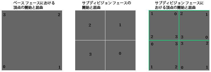
上の図は、ベース フェース(左)と、1 レベルのサブディビジョンが適用されたときのサブディバイドされたフェースと頂点の開始点と巻上げ方向(中央と右のイメージ)を示しています。サブディバイドされたフェースの開始点はベース フェースの 2 番目(インデックスが 1)の頂点と揃っていて、開始頂点はサブディバイドされたフェースの番号に基づいて移動し続けます。
サンプル コードを以下に示します。OpenSubdiv アルゴリズムと異なるコードのセクションは、太字で強調表示されています。
// Get the UV of the bottom-left corner of the subdivided face.
//
// - subdFaceIndex, the index of subdivided face within a base face
// - subdLevel, the Catmull-Clark subdivision level
//
// such that:
//
// - subdLevel >= 1.
// - 0 <= subdFaceIndex <= 4^subdLevel,
// - the uv is encoded as integer within [0, 2^subdLevel].
//
getSubFaceUV(subdFaceIndex, subdLevel) {
    uv = (0,0);
    start = 1;

    count = pow(4, subdLevel - 1);
    ofs = pow(2, subdLevel - 1);

    // Iteratively find the index of parent face in each subdivision level,
    // and offset the UV's accordingly.
    faceIndex = subdFaceIndex;
    while (count > 0) {
        // Unlike OSD subdivided topology, the start position of the child face
        // is related to that of the parent face.
        start = (start + faceIndex / count) % 4;
        switch (start) {
            case 0:                  break;
            case 1: uv += (ofs,0);   break;
            case 2: uv += (ofs,ofs); break;
            case 3: uv += (0,ofs);   break;
        }

        faceIndex %= count;
        ofs >>= 1;
        count >>= 2;
    }
    // The start position of the face is also returned.
    return (uv, start);
}

// Get the uv of the vertex on the subdivided face.
//
// - subdFaceStartUV, the UV of the bottom-left corner of the subdivided face.
// - subdVertexIndex, vertex index on the subdivided face, 0~3.
//
getSubVertexUV(subFaceStartIndex, subFaceStartUV, subdVertexIndex) {
    uv = (0,0);
    // Unlike OSD subdivided topology, the start of the vertex relies on
    // the start position of the face.
    start = (subdFaceIndex - 1 + 4) % 4;
    switch ((start + subdVertexIndex) % 4) {
        case 0:              break;
        case 1: uv += (1,0); break;
        case 2: uv += (1,1); break;
        case 3: uv += (0,1); break;
    }
    return subFaceStartUV + uv;
}

(subdFaceStartUV, start) = getSubFaceUV(subdFaceIndex, subdLevel);
subdVertexUV = getSubVertexUV(start, subdFaceStartUV, subdVertexIndex);
subdVertexUV /= pow(2, subdLevel);
データのリマッピング インタフェース
ビューポート 1 とビューポート 2.0 の両方で、適切なハードウェア シェーダ インタフェースを介して次のデータ バッファの要件を指定することで、リマッピングされたデータを取得できます。次のリマッピング データが現在使用できます。
-
頂点 ID
-
フェース ID
-
フェース単位のローカル パラメータ設定
描画時に先ほど説明したロジックを使用してリマッピングを計算する代わりに、このデータを直接使用できます。さらに、このデータはキャッシュされ、トポロジ操作がポリゴン シェイプに影響を与えるときにのみ必要に応じて更新されます。
オブジェクトのジオメトリが表示用にスムーズされていない場合:
- オリジナル フェースの ID が昇順で返されます。
-
オリジナルの頂点の ID がフェースごとに返されます。
-
ローカル パラメータ設定がフェースごとの単位正方形まで縮退します。
表示用のスムージングが有効になっている場合:
-
ベース フェースの ID が返されます。順序はサブディバイドされたフェースごとに昇順です。
-
サブディバイドされた頂点の ID が返されます。順序はサブディバイドされたフェースごとに昇順です。表示用に頂点が生成される可能性があるため、ベース メッシュの頂点と対応しない頂点 ID があります。必要に応じて、これらの頂点を MFnMesh インタフェースを介して抽出されたスムーズ メッシュ ジオメトリの頂点 ID と一致させることができます。
-
ローカル パラメータ設定はベース フェースの単位正方形に各頂点をマッピングします。順序はサブディバイドされたフェースごとに昇順です。
VP2 バッファへの要求に共有されていないデータへの要求が含まれている限り、VP1 と VP2 に返されるデータ バッファのデータと順序は一貫しています。VP1 は常に共有されていないデータを返します。
リマッピングのために追加データが必要な場合には、オブジェクト レベル(カラー セットなど)で頂点単位のストリームを追加することで行うことができます。
ビューポート 1: MPxHwShaderNode アクセス
追加情報を要求するために、次の API メソッドを MPxHwShaderNode から派生するクラスでオーバーライドできます。
- 頂点 ID は次のメソッドのオーバーライドによって要求できます。
- フェース ID は次のメソッドのオーバーライドによって要求できます。
- ローカル パラメータ設定は次のメソッドのオーバーライドによって要求できます。
- bool MPxHwShaderNode::provideLocalUVCoord ()
この情報は、MPxHwShaderNode::geometry()メソッドまたは MPxHwShaderNode::glGeometry()メソッドを介して CPU データ バッファとしてキャッシュされ、返されます。glGeometry() の署名は次のとおりです。
MStatus MPxHwShaderNode::glGeometry( const MDagPath& shapePath,
    int prim,
    unsigned int writable,
    int indexCount,
    const unsigned int * indexArray,
    int vertexCount,
    const int * vertexIDs,
    const float* vertexArray,
    int normalCount,
    floatArrayPtr normalArrays,
    int colorCount,
    floatArrayPtr colorArrays,
    int texCoordCount,
    floatArrayPtr texCoordArrays,
    const int * faceIDs,
    const float * localUVCoord)
このデータを取得するためのサンプル コードが、hwPhongShader プラグイン サンプルにあります。glGeometry() メソッドの実装のコード サンプルを以下に示します。
// Dump out vertexIDs
if (vertexIDs)
{
    for (int i=0; i<vertexCount; i++)
    {
        printf("%d\n", vertexIDs[i]);
    }
}

// Dump out face IDs
if (faceIDs)
{
    for (int i=0; i<vertexCount; i++)
    {
        printf("%d\n", faceIDs[i]);
    }
}
}

// Dump out float pairs for the local parameterization (UV)
if (localUVCoord)
{
    for (int i = 0; i < vertexCount; i++)
    {
        printf("(%g, %g)\n", localUVCoord[i*2], localUVCoord[i*2 + 1]);
    }
}
ビューポート 2.0: MPxShaderOverride のアクセス
既定では、VP2 は完全に共有されていないデータを返しません。次を介してこの要件を指定するための新しいインタフェースが追加されています。
-
bool MPxShaderOverride::requiresUnsharedGeometricSteams()
プラグインはこのメソッドをオーバーライドして、ジオメトリ ストリームの拡大を強制するために true を返すことができます。
フェース ID、頂点 ID、またはローカル パラメータ設定を取得するために、(MPxShaderOverride の新しいインタフェースの代わりに)次のセマンティックが追加されています。
-
vertexid: 設定すると頂点 ID バッファが返されます
-
faceid: 設定するとフェース ID バッファが返されます
-
localuvcoord: 設定するとローカル UV 座標バッファが返されます
hwPhongShader プラグイン サンプルの次のサンプル コードは、initialize()メソッド内で 3 つの追加のストリームを指定します。
// Ask for vertex IDs
MHWRender::MVertexBufferDescriptor vertexIdDesc(
    empty,
    MHWRender::MGeometry::kTexture,
    MHWRender::MGeometry::kFloat,
    1);
vertexIdDesc.setSemanticName("vertexid");
addGeometryRequirement(vertexIdDesc);

// Ask for face IDs
MHWRender::MVertexBufferDescriptor faceIdDesc(
    empty,
    MHWRender::MGeometry::kTexture,
    MHWRender::MGeometry::kFloat,
    1);
faceIdDesc.setSemanticName("faceid");
addGeometryRequirement(faceIdDesc);

// Ask for local parameterization data
MHWRender::MVertexBufferDescriptor localUvCoordDesc(
    empty,
    MHWRender::MGeometry::kTexture,
    MHWRender::MGeometry::kFloat,
    1);
faceIdDesc.setSemanticName("localuvcoord");
addGeometryRequirement(localUvCoordDesc);
(同じプラグインの)サンプル抽出コードを以下に示します。
for (int vbIdx=0; vbIdx<geometry->vertexBufferCount(); vbIdx++)
{
    const MHWRender::MVertexBuffer* vb = geometry->vertexBuffer(vbIdx);
    if (!vb) continue;

    const MHWRender::MVertexBufferDescriptor& desc = vb->descriptor();
    if (desc.dimension() != 1) continue;

    // Check if semantic is for the streams we’re looking for.
    MString semanticName = desc.semanticName();

    // Dump out local parameterization. Each pair of float values gives
    // a local UV on the base face.
    if (semanticName == "localuvcoord")
    {
        // Cancel constness to map buffer and dump data.
        MHWRender::MVertexBuffer*
        nonConstVB = const_cast<MHWRender::MVertexBuffer*>(vb);

        const float *ptr = (const float*)nonConstVB->map();
        for (unsigned int k = 0; k < vb->vertexCount(); k++)
        {
            printf("%s[%d] = (%g, %g)\n", semanticName.asChar(),
                k, ptr[2*k], ptr[2*k + 1]);
        }
        nonConstVB->unmap();
    }

    // Dump out vertex or face identifiers. If smoothed the vertex ids will be
    // the smoothed ids, but the face ids are always the base face ids.
    //
    if (semanticName != "vertexid" && semanticName != "faceid") continue;

    MHWRender::MVertexBuffer* nonConstVB = const_cast<MHWRender::MVertexBuffer*>(vb);
    const float *ptr = (const float*)nonConstVB->map();
    for (unsigned int k=0; k<vb->vertexCount(); k++)
    {
        printf("%s[%d] = %f\n", semanticName.asChar(), k, ptr[k] );
    }
    nonConstVB->unmap();
}
ビューポート 2.0: MGeometryExtractor のアクセス

ビューポート 2.0 では、MGeometryExtractor インタフェースを介して頂点 ID、フェース ID、およびローカル パラメータ配置のアクセスも公開されます。完全に共有されていないジオメトリ データを DAG シェイプから抽出するには、MGeometryExtractor インスタンスを構築するときに kPolyGeom_NotSharing を指定する必要があります。
ここに geometryReplicator プラグインのサンプル コードを示します。
MStatus status;
MHWRender::MPolyGeomOptions options = MHWRender::kPolyGeom_Normal;
if (requiresUnsharedGeometricStreams(requirements))
{
    options = options | MHWRender::kPolyGeom_NotSharing;
}
MHWRender::MGeometryExtractor extractor(requirements, fPath, options, &status);
次のコード スニペットは、geometryReplicator プラグインが、ジオメトリ要件に応じて、共有されていないデータを必要とするかどうかを決定する方法を示しています。
bool requiresUnsharedGeometricStreams(const MHWRender::MGeometryRequirements& requirements)
{
    // Only when vertexid, faceid or localuvcoord is required do the unshared geometric
    // streams need to be extracted
    const MHWRender::MVertexBufferDescriptorList& descList = requirements.vertexRequirements();
    for (int reqNum = 0; reqNum < descList.length(); ++reqNum)
    {
        MHWRender::MVertexBufferDescriptor desc;
        if (descList.getDescriptor(reqNum, desc) &&
            desc.semantic() == MHWRender::MGeometry::kTexture)
        {
            const MString semanticName = desc.semanticName();
            if (semanticName == "vertexid" ||
                semanticName == "faceid" ||
                semanticName == "localuvcoord")
            {
                    return true;
            }
        }
    }
    return false;
}
MPxShaderOverride と同様、頂点 ID、フェース ID、およびローカル パラメータ配置を要求する MGeometryExtractor に新しいインタフェースはありません。これらの頂点バッファを設定するには、次のセマンティック名を使用して MVertexBufferDescriptor を指定する必要があります。
- “vertexid”: 設定すると頂点 ID バッファが返されます
- “faceid”: 設定するとフェース ID バッファが返されます
- “localuvcoord”: 設定するとローカル UV 座標バッファが返されます
これらのセマンティック名は geometryReplicator プラグインでは直接指定されませんが、geometryReplicator ノードに hwPhongShader が割り当てられている場合、これらはジオメトリ要件に含まれます。次の例は、これらを明示的に指定する方法を示しています。
// Request vertex IDs (or face IDs, local parameterization)
MHWRender::MVertexBufferDescriptor vertexIdDesc(
    empty,
    MHWRender::MGeometry::kTexture,
    MHWRender::MGeometry::kFloat,
    1);
vertexIdDesc.setSemanticName("vertexid");

// Create a vertex buffer via MGeometry interface, extract and fill the data.
MHWRender::MVertexBuffer vertexBuffer = geometry.createVertexBuffer(vertexIdDesc);
unsigned int vertexCount = extractor.vertexCount();
float* data = (float*)vertexBuffer->acquire(vertexCount, true);
if (data && extractor.populateVertexBuffer(data, vertexCount, vertexIdDesc))
{
    vertexBuffer->commit(data);
}
インデックス バッファを介してデータにアクセスする
レンダー時に提供されるインデックス バッファは、三角形ごとにデータ バッファにアクセスするために使用できます。
VP1 には統合がなく、頂点は共有されていないため、3 つごとのインデックスがフェースの昇順で三角形の頂点 ID を参照します。
VP2 の場合、統合を行うとインデックス バッファに部分的な範囲のセットが生成される場合があります。統合された各オブジェクトに使用されるデータを各範囲が示します。不明瞭なマッピングを回避するために、常に共有されていないデータを要求する必要があります。範囲の処理の詳細については、「統合に関する考慮事項」を参照してください。
hwPhongShader プラグインには、VP1 と VP2 両方のためのインデックス情報を抽出する方法を示すサンプル コードが含まれています。VP2 用に、範囲処理サンプル デバッグ コードが提供されています。
例 1: スムーズされていない四角形
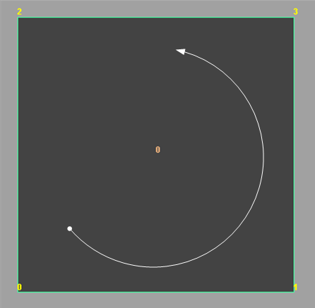
行われるリマッピングを検討するために、追加データ バッファを抽出するための API を使用する hwPhongShader プラグインがサンプルに使用されています。この場合、上に示したようにそのシェーダのインスタンスが単一の四角形のシェイプに割り当てられます。ベース フェース ID と頂点 ID、開始頂点(ドット)、巻上げ方向(曲がった矢印)が表示されます。
レンダー時のバッファは次のようになります。
| 頂点 ID (反時計回りの巻上げ) | フェース ID | ローカル UV |
|---|---|---|
| 0 | 0 | (0, 0) |
| 1 | 0 | (0, 1) |
| 3 | 0 | (1, 1) |
| 2 | 0 | (1, 0) |
例 2: スムーズ レベル 1 の四角形 - OpenSubdiv Catmull-Clark
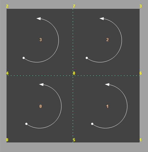
上に示したトポロジは、OpenSubdiv を使用した 1 レベルのスムージングを示しています。サブフェースとサブ頂点ごとの開始点と巻上げ方向は、すべてのレベルとベース フェースで一貫しています。
データ バッファは次のようになります。次の点に注意してください。
-
上記のトポロジとの相関関係を示すためにサブフェース ID 列が追加されていますが、個別の頂点バッファとしては提供されていません。
-
頂点 ID 6 ~ 8 は、ベース メッシュの一部ではありません。
頂点 ID 4、5、6、7、8 は、スムージングの一部として導入された頂点です。ベース メッシュには頂点 0、1、2、3 があります。点線はスムージング操作によって行われたサブディビジョンの位置を示します。
-
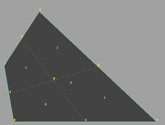
ローカル パラメータ設定は、単にベース頂点に関連した補間を示すために値を提供しています。ベース フェース内の頂点の実際の配置とは関係ありません。たとえば、次のジオメトリのように頂点 8 が実際には頂点 0 の近くに配置されている場合も、ローカル UV 値は(0.5,0.5)になります。
| 頂点 ID (反時計回り) | フェース ID | サブフェース ID | ローカル UV |
|---|---|---|---|
| 0 | 0 | 0 | (0, 0) |
| 5 | 0 | 0 | (0, 0.5) |
| 8 | 0 | 0 | (0.5, 0.5) |
| 4 | 0 | 0 | (0.5, 0) |
| 5 | 0 | 1 | (0, 0.5) |
| 1 | 0 | 1 | (0, 1) |
| 6 | 0 | 1 | (0.5, 1) |
| 8 | 0 | 1 | (0.5, 0.5) |
| 8 | 0 | 2 | (0.5, 0.5) |
| 6 | 0 | 2 | (0.5, 1) |
| 3 | 0 | 2 | (1, 1) |
| 7 | 0 | 2 | (1, 0.5) |
| 4 | 0 | 3 | (0.5, 0) |
| 8 | 0 | 3 | (0.5, 0.5) |
| 7 | 0 | 3 | (1, 0.5) |
| 2 | 0 | 3 | (1, 0) |
提供されたインデックス バッファは三角形ごとの情報へのアクセスに使用できます。
前述のとおり、三角形分割がポリゴン シェイプの quadSpit アトリビュートに指定された値と一致しない場合があります。次の三角形分割が与えられた場合、
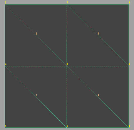
インデックス バッファは次のようになります。
| 三角形の番号 | 頂点 ID |
|---|---|
| 0 | 0 |
| 0 | 5 |
| 0 | 4 |
| 1 | 4 |
| 1 | 5 |
| 1 | 8 |
| 2 | 5 |
| 2 | 1 |
| 2 | 8 |
| 3 | 8 |
| 3 | 1 |
| 3 | 6 |
| 4 | 8 |
| 4 | 6 |
| 4 | 7 |
| 5 | 7 |
| 5 | 6 |
| 5 | 3 |
| 6 | 4 |
| 6 | 8 |
| 6 | 2 |
| 7 | 2 |
| 7 | 8 |
| 7 | 7 |
例 3: スムーズ レベル 1 の四角形 - 旧式の Catmull-Clark
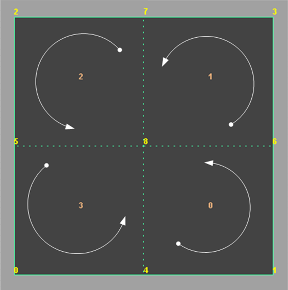
上記のトポロジは、旧式の Catmull-Clark サブディビジョン メソッドを使用したレベル 1 のスムージングを示しています。サブフェースとサブ頂点の開始点の移動が確認できます。
データ バッファは次のようになります。例 2 のように、上記のトポロジとの相関関係を示すためにサブフェース ID 列が追加されていますが、バッファとしては提供されていません。
サブフェースとサブ頂点の開始位置の移動は、図に示された内容を反映しています。
| 頂点 ID (反時計回り) | フェース ID | サブフェース ID | ローカル UV |
|---|---|---|---|
| 4 | 0 | 0 | (0, 0.5) |
| 1 | 0 | 0 | (0, 1) |
| 6 | 0 | 0 | (0.5, 1) |
| 8 | 0 | 0 | (0.5, 0.5) |
| 6 | 0 | 1 | (0.5, 1) |
| 3 | 0 | 1 | (1, 1) |
| 7 | 0 | 1 | (1, 0.5) |
| 8 | 0 | 1 | (0.5, 0.5) |
| 7 | 0 | 2 | (1, 0.5) |
| 2 | 0 | 2 | (1, 0) |
| 5 | 0 | 2 | (0.5, 0) |
| 8 | 0 | 2 | (0.5, 0.5) |
| 5 | 0 | 3 | (0.5, 0) |
| 0 | 0 | 3 | (0, 0) |
| 4 | 0 | 3 | (0, 0.5) |
| 8 | 0 | 3 | (0.5, 0.5) |
開始フェースと開始頂点が異なるという事実に基づいて、旧式の Catmull-Clark は、OpenSubdiv Catmull-Clark とは異なるインデックスを使用しています。そのため、同じ例を使用すると、三角形分割は次のようになります。
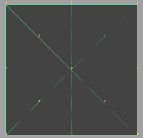
インデックスは次のようになります。
| 三角形の番号 | 頂点 ID |
|---|---|
| 0 | 4 |
| 0 | 1 |
| 0 | 8 |
| 1 | 8 |
| 1 | 1 |
| 1 | 6 |
| 2 | 6 |
| 2 | 3 |
| 2 | 8 |
| 3 | 8 |
| 3 | 3 |
| 3 | 7 |
| 4 | 7 |
| 4 | 2 |
| 4 | 8 |
| 5 | 8 |
| 5 | 2 |
| 5 | 5 |
| 6 | 5 |
| 6 | 0 |
| 6 | 8 |
| 7 | 8 |
| 7 | 0 |
| 7 | 4 |
例 4: スムーズ レベル 2 の四角形 - 旧式の Catmull-Clark
次のイメージは、旧式の Catmull-Clark メソッドを使用したレベル 2 のサブディビジョンと、サブディビジョン パターンの繰り返しを示しています。
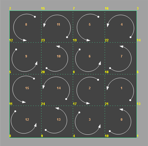
hwPhongShader プラグインから次のデータがトレースされます。
| 頂点 ID (反時計回り) | フェース ID | サブフェース ID | ローカル UV |
|---|---|---|---|
| 10 | 0 | 0 | (0, 0.75) |
| 1 | 0 | 0 | (0, 1) |
| 13 | 0 | 0 | (0.25, 1) |
| 21 | 0 | 0 | (0.25, 0.75) |
| 13 | 0 | 1 | (0.25, 1) |
| 6 | 0 | 1 | (0.5, 1) |
| 18 | 0 | 1 | (0.5, 0.75) |
| 21 | 0 | 1 | (0.25, 0.75) |
| 18 | 0 | 2 | (0.5, 0.75) |
| 8 | 0 | 2 | (0.5, 0.5) |
| 17 | 0 | 2 | (0.25, 0.5) |
| 21 | 0 | 2 | (0.25, 0.75) |
| 17 | 0 | 3 | (0.25, 0.5) |
| 4 | 0 | 3 | (0, 0.5) |
| 10 | 0 | 3 | (0, 0.75) |
| 21 | 0 | 3 | (0.25, 0.75) |
| 14 | 0 | 4 | (0.75, 1) |
| 3 | 0 | 4 | (1, 1) |
| 16 | 0 | 4 | (1, 0.75) |
| 22 | 0 | 4 | (0.75, 0.75) |
| 16 | 0 | 5 | (1, 0.75) |
| 7 | 0 | 5 | (1, 0.5) |
| 19 | 0 | 5 | (0.75, 0.5) |
| 22 | 0 | 5 | (0.75, 0.75) |
| 19 | 0 | 6 | (0.75, 0.5) |
| 8 | 0 | 6 | (0.5, 0.5) |
| 18 | 0 | 6 | (0.5, 0.75) |
| 22 | 0 | 6 | (0.75, 0.75) |
| 18 | 0 | 7 | (0.5, 0.75) |
| 6 | 0 | 7 | (0.5, 1) |
| 14 | 0 | 7 | (0.75, 1) |
| 22 | 0 | 7 | (0.75, 0.75) |
| 15 | 0 | 8 | (1, 0.25) |
| 2 | 0 | 8 | (1, 0) |
| 12 | 0 | 8 | (0.75, 0) |
| 23 | 0 | 8 | (0.75, 0.25) |
| 12 | 0 | 9 | (0.75, 0) |
| 5 | 0 | 9 | (0.5, 0) |
| 20 | 0 | 9 | (0.5, 0.25) |
| 23 | 0 | 9 | (0.75, 0.25) |
| 20 | 0 | 10 | (0.5, 0.25) |
| 8 | 0 | 10 | (0.5, 0.5) |
| 19 | 0 | 10 | (0.75, 0.5) |
| 23 | 0 | 10 | (0.75, 0.25) |
| 19 | 0 | 11 | (0.75, 0.5) |
| 7 | 0 | 11 | (1, 0.5) |
| 15 | 0 | 11 | (1, 0.25) |
| 23 | 0 | 11 | (0.75, 0.25) |
| 11 | 0 | 12 | (0.25, 0) |
| 0 | 0 | 12 | (0, 0) |
| 9 | 0 | 12 | (0, 0.25) |
| 24 | 0 | 12 | (0.25, 0.25) |
| 9 | 0 | 13 | (0, 0.25) |
| 4 | 0 | 13 | (0, 0.5) |
| 17 | 0 | 13 | (0.25, 0.5) |
| 24 | 0 | 13 | (0.25, 0.25) |
| 17 | 0 | 14 | (0.25, 0.5) |
| 8 | 0 | 14 | (0.5, 0.5) |
| 20 | 0 | 14 | (0.5, 0.25) |
| 24 | 0 | 14 | (0.25, 0.25) |
| 20 | 0 | 15 | (0.5, 0.25) |
| 5 | 0 | 15 | (0.5, 0) |
| 11 | 0 | 15 | (0.25, 0) |
| 24 | 0 | 15 | (0.25, 0.25) |
