この要素タイプには、プロジェクトやファミリ ドキュメントでの読み込み操作や計算で取得した任意のジオメトリを格納できます。
DirectShape 要素と関連するクラスは、外部で作成されたジオメトリの形状を Revit ドキュメントに格納する機能をサポートします。ジオメトリには閉じたソリッドやメッシュを含めることができます。DirectShape は、「実際の」Revit 要素を作成するための十分な情報が利用できない IFC や STEP といった他のデータ形式から形状を読み込むことを主な目的としています。
DirectShape オブジェクトは、Wall カテゴリなどの最上位の Model カテゴリに割り当てることができます。DirectShape 要素にサブカテゴリを割り当てることはできません。IsValidCategoryId() メソッドを使用すると、カテゴリ ID を検証して、それが DirectShape での使用を承認された最上位の組み込みカテゴリであることを確認できます。Category.CategoryType 列挙値は、カテゴリ タイプが Model であるかどうかを示します。カテゴリを割り当てると、Revit でのオブジェクトの表示方法が影響を受け、利用可能なパラメータのコレクションといくつかの制限された動作がオブジェクトに付与されます。
DirectShape の作成
静的 CreateElement()メソッドは、インスタンス レベルの新しい DirectShape を作成します。DirectShape が追加されるドキュメントと適切な組み込みカテゴリの ID が必要です。DirectShape には追加のフィールドがあります。これは、DirectShape 要素を管理するために、作成するアプリケーションによって使用され、2 つの文字列パラメータを CreateElement()に渡します。これらのフィールドには、作成した形状のソースのコンテキストを取得するために、必要に応じて後でアプリケーションからアクセスできます。
DirectShape を作成したら、オーバーロードしたいずれかの SetShape()メソッドを使用して形状を設定できます。形状は ShapeBuilder オブジェクトから直接設定することも、GeometryObjects のリストから設定することもできます。ShapeBuilder オブジェクトを使用して DirectShape のジオメトリを構築する場合、ShapeBuilder 入力を使用すると Revit で入力ジオメトリを繰り返し検証しなくても済むため、パフォーマンスがわずかに向上します。AppendShape ()メソッドのバージョンを使用すると、DirectShape にジオメトリ オブジェクトを追加することもできます。AppendShape()では受け取ったジオメトリを既に存在するジオメトリに合成または結することはできません。ジオメトリは別々に格納されます。
DirectShape では次のジオメトリ タイプを入力として使用できます。
- ソリッド(閉じたシェルまたは開いたシェル)
- メッシュ
- 曲線
- 点
さらに、DirectShape のビュー固有の表現で使用するジオメトリを指定できます。このジオメトリは、DirectShapeTargetViewType の入力値とともに入力されます。ビュー固有の形状の表現を設定する場合、該当するタイプのビューでのみ使用されます。現在、サポートされているビュー固有の表現は平面図ビュー用のみです。
次の例は、GeometryCreationUtilities クラスを使用して作成された球から単純な DirectShape を作成する方法を示しています。ジオメトリ作成中に参照する Frame の使用方法に注目してください。Frame を使用してジオメトリを作成する前に、Frame.CanDefineRevitGeometry() 静的メソッドを呼び出して、供給された Frame オブジェクトが Revit の曲線やサーフェスの設定に使用できるかテストすることをお勧めします。要件を満たすには、Frame が正規直交であり、その基準点が Revit の設計制限内に収まる必要があります。(ジオメトリを作成するときに、静的な XYZ.IsWithinLengthLimits() を使用すると、点が Revit の設計制限内にあることを確認するのに役に立ちます。)
|
コード領域: DirectShape を作成 |
// Create a DirectShape Sphere
public void CreateSphereDirectShape(Document doc)
{
    List<Curve> profile = new List<Curve>();

    // first create sphere with 2' radius
    XYZ center = XYZ.Zero;
    double radius = 2.0;
    XYZ profile00 = center;
    XYZ profilePlus = center + new XYZ(0, radius, 0);
    XYZ profileMinus = center - new XYZ(0, radius, 0);

    profile.Add(Line.CreateBound(profilePlus, profileMinus));
    profile.Add(Arc.Create(profileMinus, profilePlus, center + new XYZ(radius, 0, 0)));

    CurveLoop curveLoop = CurveLoop.Create(profile);
    SolidOptions options = new SolidOptions(ElementId.InvalidElementId, ElementId.InvalidElementId);

    Frame frame = new Frame(center, XYZ.BasisX, -XYZ.BasisZ, XYZ.BasisY);
    if (Frame.CanDefineRevitGeometry(frame) == true)
    {
        Solid sphere = GeometryCreationUtilities.CreateRevolvedGeometry(frame, new CurveLoop[] { curveLoop }, 0, 2 * Math.PI, options);
        using (Transaction t = new Transaction(doc, "Create sphere direct shape"))
        {
            t.Start();
            // create direct shape and assign the sphere shape
            DirectShape ds = DirectShape.CreateElement(doc, new ElementId(BuiltInCategory.OST_GenericModel));

            ds.ApplicationId = "Application id";
            ds.ApplicationDataId = "Geometry object id";
            ds.SetShape(new GeometryObject[] { sphere });
            t.Commit();
        }
    }
}
|
DirectShape のジオメトリは、ShapeBuilder クラスのサブクラスを使用して作成することも、TessellatedShapeBuilder から作成することもできます。
ShapeBuilder
ViewShapeBuilder や WireframeBuilder を使用すると DirectShape クラスに格納するジオメトリを作成できます。ViewShapeBuilder クラスはビュー固有の形状の表現を構築、検証します。これは、平面図ビューの曲線をベースにした表現に限定されます。WireframeBuilder は点と曲線で構成される 3D 形状表現を作成します。ShapeBuilders の両方のタイプとも、ShapeBuilder パラメータを使用する DirectShape.SetShape()または DirectShape.AppendShape()オーバーロードを使って DirectShape 要素に適用できます。
TessellatedShapeBuilder
TessellatedShapeBuilder を使用すると、接続された一連の切り子面を境界に持つソリッド、シェル、ポリメッシュを作成できます。これは TessellatedFace オブジェクトを 1 つずつ追加することによって作成されます。面は面のセットが「開いている」場合にのみ、ビルドに追加できます。面のセットを開くには、OpenConnectedFaceSet()メソッドを使用します。すべての TessellatedFaces を追加したら、CloseConnecedFaceSet() を呼び出して面のセットを閉じます。ビルダでは複数の面のセットを使用できます。そのような場合、最初のセットがボディの外側の「サーフェス」を表し、それ以後のセットが内部のボイドを表します。入力されたデータに矛盾や欠落がある場合でも、ビルダは、Revit で有効なジオメトリを作成しようとします。
すべての面を設定して面のセットを閉じたら、Build()メソッドを呼び出して、格納されている面のセットから指定したジオメトリ オブジェクトを作成します。Build() を呼び出す前に TessellatedShapeBuilder の Target プロパティ、Fallback プロパティ、GraphicsStyleId プロパティを設定することができます。設定せずに呼び出した場合、既定のオプションが使用されます。Build() の結果値が TessellatedShapeBuilder に格納されます。この値は GetBuildResult() を呼び出すことで取得できます。次の例に示すように、TessellatedShapeBuilderResult.GetGeometricalObjects()メソッドは、対応する DirectShape.SetShape()や DirectShape.AppendShape()オーバーロードで使用できる GeometryObjects のリストを返します。
|
コード領域: TessellatedShapeBuilder を使用して DirectShape を作成 |
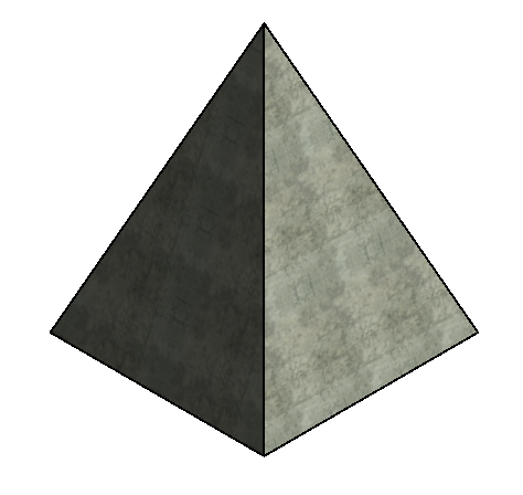
// Create a pyramid-shaped DirectShape using given material for the faces
public void CreateTessellatedShape(Document doc, ElementId materialId)
{
    List<XYZ> loopVertices = new List<XYZ>(4);

    TessellatedShapeBuilder builder = new TessellatedShapeBuilder();

    builder.OpenConnectedFaceSet(true);
    // create a pyramid with a square base 4' x 4' and 5' high
    double length = 4.0;
    double height = 5.0;

    XYZ basePt1 = XYZ.Zero;
    XYZ basePt2 = new XYZ(length, 0, 0);
    XYZ basePt3 = new XYZ(length, length, 0);
    XYZ basePt4 = new XYZ(0, length, 0);
    XYZ apex = new XYZ(length / 2, length / 2, height);

    loopVertices.Add(basePt1);
    loopVertices.Add(basePt2);
    loopVertices.Add(basePt3);
    loopVertices.Add(basePt4);
    builder.AddFace(new TessellatedFace(loopVertices, materialId));

    loopVertices.Clear();
    loopVertices.Add(basePt1);
    loopVertices.Add(apex);
    loopVertices.Add(basePt2);
    builder.AddFace(new TessellatedFace(loopVertices, materialId));

    loopVertices.Clear();
    loopVertices.Add(basePt2);
    loopVertices.Add(apex);
    loopVertices.Add(basePt3);
    builder.AddFace(new TessellatedFace(loopVertices, materialId));

    loopVertices.Clear();
    loopVertices.Add(basePt3);
    loopVertices.Add(apex);
    loopVertices.Add(basePt4);
    builder.AddFace(new TessellatedFace(loopVertices, materialId));

    loopVertices.Clear();
    loopVertices.Add(basePt4);
    loopVertices.Add(apex);
    loopVertices.Add(basePt1);
    builder.AddFace(new TessellatedFace(loopVertices, materialId));

    builder.CloseConnectedFaceSet();
    builder.Target = TessellatedShapeBuilderTarget.Solid;
    builder.Fallback = TessellatedShapeBuilderFallback.Abort;
    builder.Build();

    TessellatedShapeBuilderResult result = builder.GetBuildResult();

    using (Transaction t = new Transaction(doc, "Create tessellated direct shape"))
    {
        t.Start();

        DirectShape ds = DirectShape.CreateElement(doc, new ElementId(BuiltInCategory.OST_GenericModel));
        ds.ApplicationId = "Application id";
        ds.ApplicationDataId = "Geometry object id";

        ds.SetShape(result.GetGeometricalObjects());
        t.Commit();
    }
}
|
下のイメージは、コンクリート マテリアル ID を指定して上の例を実行したときの結果を示しています。
BRepBuilder
BRepBuilder クラスは、Revit の境界表現ジオメトリ(ソリッド、開いたシェルなど)をサーフェス、エッジ、エッジの境界ループの入力の結果として構築する機能を提供します。境界表現が正常に構築された場合は、結果として出力されるジオメトリ オブジェクトがジオメトリを受け入れる他のすべての Revit ツールで直接使用されるか、または DirectShape クラスの SetShape() メソッドと AppendShape() メソッドによって DirectShape を設定するのに BRepBuilder が直接渡されます。下記の例では、SetShape() メソッドを使用して、円柱形状を新しい DirectShape オブジェクトに割り当てています。
|
コード領域: BRepBuilder を使用して DirectShape を作成 |
private void CreateDirectShapeFromCylinder(Document doc)
{
    // Naming convention for faces and edges: we assume that x is to the left and pointing down, y is horizontal and pointing to the right, z is up
    BRepBuilder brepBuilder = new BRepBuilder(BRepType.Solid);

    // The surfaces of the four faces.
    Frame basis = new Frame(new XYZ(50, -100, 0), new XYZ(0, 1, 0), new XYZ(-1, 0, 0), new XYZ(0, 0, 1));
    CylindricalSurface cylSurf = CylindricalSurface.Create(basis, 50);
    Plane top = Plane.CreateByNormalAndOrigin(new XYZ(0, 0, 1), new XYZ(0, 0, 100));  // normal points outside the cylinder
    Plane bottom = Plane.CreateByNormalAndOrigin(new XYZ(0, 0, 1), new XYZ(0, 0, 0)); // normal points inside the cylinder

    // Add the four faces
    BRepBuilderGeometryId frontCylFaceId = brepBuilder.AddFace(BRepBuilderSurfaceGeometry.Create(cylSurf, null), false);
    BRepBuilderGeometryId backCylFaceId = brepBuilder.AddFace(BRepBuilderSurfaceGeometry.Create(cylSurf, null), false);
    BRepBuilderGeometryId topFaceId = brepBuilder.AddFace(BRepBuilderSurfaceGeometry.Create(top, null), false);
    BRepBuilderGeometryId bottomFaceId = brepBuilder.AddFace(BRepBuilderSurfaceGeometry.Create(bottom, null), true);

    // Geometry for the four semi-circular edges and two vertical linear edges
    BRepBuilderEdgeGeometry frontEdgeBottom = BRepBuilderEdgeGeometry.Create(Arc.Create(new XYZ(0, -100, 0), new XYZ(100, -100, 0), new XYZ(50, -50, 0)));
    BRepBuilderEdgeGeometry backEdgeBottom = BRepBuilderEdgeGeometry.Create(Arc.Create(new XYZ(100, -100, 0), new XYZ(0, -100, 0), new XYZ(50, -150, 0)));

    BRepBuilderEdgeGeometry frontEdgeTop = BRepBuilderEdgeGeometry.Create(Arc.Create(new XYZ(0, -100, 100), new XYZ(100, -100, 100), new XYZ(50, -50, 100)));
    BRepBuilderEdgeGeometry backEdgeTop = BRepBuilderEdgeGeometry.Create(Arc.Create(new XYZ(0, -100, 100), new XYZ(100, -100, 100), new XYZ(50, -150, 100)));

    BRepBuilderEdgeGeometry linearEdgeFront = BRepBuilderEdgeGeometry.Create(new XYZ(100, -100, 0), new XYZ(100, -100, 100));
    BRepBuilderEdgeGeometry linearEdgeBack = BRepBuilderEdgeGeometry.Create(new XYZ(0, -100, 0), new XYZ(0, -100, 100));

    // Add the six edges
    BRepBuilderGeometryId frontEdgeBottomId = brepBuilder.AddEdge(frontEdgeBottom);
    BRepBuilderGeometryId frontEdgeTopId = brepBuilder.AddEdge(frontEdgeTop);
    BRepBuilderGeometryId linearEdgeFrontId = brepBuilder.AddEdge(linearEdgeFront);
    BRepBuilderGeometryId linearEdgeBackId = brepBuilder.AddEdge(linearEdgeBack);
    BRepBuilderGeometryId backEdgeBottomId = brepBuilder.AddEdge(backEdgeBottom);
    BRepBuilderGeometryId backEdgeTopId = brepBuilder.AddEdge(backEdgeTop);

    // Loops of the four faces
    BRepBuilderGeometryId loopId_Top = brepBuilder.AddLoop(topFaceId);
    BRepBuilderGeometryId loopId_Bottom = brepBuilder.AddLoop(bottomFaceId);
    BRepBuilderGeometryId loopId_Front = brepBuilder.AddLoop(frontCylFaceId);
    BRepBuilderGeometryId loopId_Back = brepBuilder.AddLoop(backCylFaceId);

    // Add coedges for the loop of the front face
    brepBuilder.AddCoEdge(loopId_Front, linearEdgeBackId, false);
    brepBuilder.AddCoEdge(loopId_Front, frontEdgeTopId, false);
    brepBuilder.AddCoEdge(loopId_Front, linearEdgeFrontId, true);
    brepBuilder.AddCoEdge(loopId_Front, frontEdgeBottomId, true);
    brepBuilder.FinishLoop(loopId_Front);
    brepBuilder.FinishFace(frontCylFaceId);

    // Add coedges for the loop of the back face
    brepBuilder.AddCoEdge(loopId_Back, linearEdgeBackId, true);
    brepBuilder.AddCoEdge(loopId_Back, backEdgeBottomId, true);
    brepBuilder.AddCoEdge(loopId_Back, linearEdgeFrontId, false);
    brepBuilder.AddCoEdge(loopId_Back, backEdgeTopId, true);
    brepBuilder.FinishLoop(loopId_Back);
    brepBuilder.FinishFace(backCylFaceId);

    // Add coedges for the loop of the top face
    brepBuilder.AddCoEdge(loopId_Top, backEdgeTopId, false);
    brepBuilder.AddCoEdge(loopId_Top, frontEdgeTopId, true);
    brepBuilder.FinishLoop(loopId_Top);
    brepBuilder.FinishFace(topFaceId);

    // Add coedges for the loop of the bottom face
    brepBuilder.AddCoEdge(loopId_Bottom, frontEdgeBottomId, false);
    brepBuilder.AddCoEdge(loopId_Bottom, backEdgeBottomId, false);
    brepBuilder.FinishLoop(loopId_Bottom);
    brepBuilder.FinishFace(bottomFaceId);

    brepBuilder.Finish();

    using (Transaction tr = new Transaction(doc, "Create a DirectShape"))
    {
        tr.Start();
        DirectShape ds = DirectShape.CreateElement(doc, new ElementId(BuiltInCategory.OST_GenericModel));
        ds.SetShape(brepBuilder);
        tr.Commit();
    }
}
|
ShapeImporter
ShapeImporter ユーティリティ クラスは、外部の形式(SAT や Rhino など)で保存されたジオメトリを、DirectShape の形状設定に使用できる GeometryObject の集合に変換する操作をサポートします。そのジオメトリ オブジェクト(に加え、可能な場合に関連ドキュメント内の該当マテリアルおよびグラフィックス スタイル)を生成するには、ShapeImporter.Convert() を使用します。
|
コード領域: SAT ファイルから DirectShape を作成 |
public void ReadSATFile(Document revitDoc)
{
    // Allow the user to select a SAT file.
    OpenFileDialog ofd = new OpenFileDialog();
    ofd.Filter = "SAT Files (*.sat)|*.sat";

    if (DialogResult.OK == ofd.ShowDialog())
    {
        ShapeImporter shapeImporter = new ShapeImporter();
        shapeImporter.InputFormat = ShapeImporterSourceFormat.SAT;
        IList<GeometryObject> shapes = shapeImporter.Convert(revitDoc, ofd.FileName);

        if (shapes.Count != 0)
        {
            using (Transaction tr = new Transaction(revitDoc, "Create a DirectShape"))
            {
                tr.Start();

                DirectShape dsImportedSat = DirectShape.CreateElement(revitDoc, new ElementId(BuiltInCategory.OST_Walls));
                dsImportedSat.SetShape(shapes);

                tr.Commit();
            }
        }
    }
}
|
オプション
DirectShapeOptions クラスを使用すると、DirectShape オブジェクトの動作をコントロールできます。DirectShape オブジェクトで使用するオプションを設定するには、DirectShape.SetOptions()を使用します。GetOptions()メソッドは、現在 DirectShape オブジェクトが使用している DirectShapeOptions を返します。
既定では、DirectShape 要素は、寸法、位置合わせ、面のホスト、スナップなどの要素参照をサポートします。この既定の動作は DirectShapeOptions.ReferencingOption プロパティを使用して変更できます。このプロパティが、NotReferenceable と設定されている場合には、寸法設定、スナップ、位置合わせ、面のホストにジオメトリを使用できない場合があります。ただし、個々のジオメトリ オブジェクトを参照しない操作であれば、ユーザが要素を選択できる場合があります。
さらに、DirectShape 要素が部屋の境界の計算に適したカテゴリであり、関連する「部屋の境界」パラメータが true に設定されている場合は、DirectShape 要素を部屋の境界の計算に加えることができます。プロパティ DirectShapeOptions.RoomBoundingOption は、DirectShape が部屋の境界の計算への参加を許可する「部屋の境界」パラメータのオプションをサポートしているかどうかを特定します。既定値は NotApplicable ですが、適用可能な DirectShape の場合は自動的に SetByParameter に変更されます。