This subassembly creates an open drainage channel with a parabolic bottom, with optional lining and backslope links.
Attachment
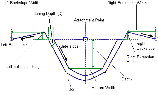
The attachment point is located above the midpoint of the bottom width, at a height equal to the Depth parameter.
Input Parameters
Note: All dimensions are in meters or feet unless otherwise noted. All slopes are in run-over-rise form (for example, 4 : 1), unless indicated as a percent slope with a “%” sign.
| Parameter | Description | Type | Default |
|---|---|---|---|
| Depth | The vertical offset down from the profile gradient line level to the bottom of the drainage channel. | Numeric, Positive |
2.0 m 6.0 ft |
| Bottom Width | Width of bottom of the drainage channel. | Numeric, Positive |
2.0 m 6.0 ft |
| Curve Tesselation Points | Number of tesselation points on parabolic curve | Integer, Positive | 7 |
| Sideslope | Drainage channel sideslopes | Numeric | 1 (:1) |
| Lining Depth | Depth of drainage channel lining. The Lining Depth is measured perpendicular to the side of the slope, as shown in the previous diagram. | Numeric, Positive |
0.1 m 0.33 ft |
| Left Marked Point | Optional marked point on the outermost drainage channel point on the left side; If no code is entered then marked point is not inserted. | String | |
| Right Marked Point | Optional marked point on the outermost drainage channel point on the right side; If no code is entered then marked point is not inserted. | String | |
| Left Extension Height | Extension of drainage channel left side over the insertion point | Numeric, Positive |
0.5 m 1.67 ft |
| Left Backslope Width | Drainage channel backfill width on left side | Numeric, Positive |
1.5 m 5.0 ft |
| Left Backslope | Drainage channel backfill slope on left side | Numeric | 4 (:1) |
| Right Extension Height | Extension of drainage channel right side over the insertion point | Numeric, Positive |
0.5 m 1.67 ft |
| Right Backslope Width | Drainage channel backfill width on the right side | Numeric, Positive |
1.25 m 5.0 ft |
| Right Backslope | Drainage channel backfill slope on right side | Numeric | 4 (:1) |
Target Parameters
This section lists the parameters in this subassembly that can be mapped to one or more target objects. For more information, see To Specify Corridor Targets.
| Parameter | Description | Status |
|---|---|---|
| Left Extension Height | May be used to override the fixed extension height on left side and tie to a profile. The following object types can be used as targets for specifying the level: profiles, 3D polylines, feature lines, or survey figures. | Optional |
| Left Backslope Width | May be used to override the fixed Left Backslope Width and tie to an offset alignment. The following object types can be used as targets for specifying the width: alignments, polylines, feature lines, or survey figures. | Optional |
| Left Backslope Level | May be used to override the fixed Left Backslope and tie to a profile. The following object types can be used as targets for specifying the level: profiles, 3D polylines, feature lines, or survey figures. | Optional |
| Right Extension Height | May be used to override the fixed extension height on right side and tie to a profile. The following object types can be used as targets for specifying the level: profiles, 3D polylines, feature lines, or survey figures. | Optional |
| Left Backslope Width | May be used to override the fixed Right Backslope Width and tie to an offset alignment. The following object types can be used as targets for specifying the width: alignments, polylines, feature lines, or survey figures. | Optional |
| Left Backslope Level | May be used to override the fixed Right Backslope and tie to a profile. The following object types can be used as targets for specifying the level: profiles, 3D polylines, feature lines, or survey figures. | Optional |
Output Parameters
None.
Behavior
This subassembly builds an open drainage channel shape using the input parameters. The attachment point is typically at the start of the baseline, at associated alignments and profiles. At the bottom left and right lower sideslope link, points are located using a specified Bottom Width parameter. A parabolic curve is drawn between these two points with gradient-in and gradient-out equal to the specified sideslope parameter. The length of the parabolic curve is equal to the Bottom Width value. This parabolic curve is drawn in tessellated links using the Curve Tessellation Points parameter. If the tessellation index is odd, then a point is added directly below the attachment point of the subassembly.
For the drainage channel lining depth, if a non-zero positive value is specified for the Lining Depth parameter, then a material lining is drawn around the drainage channel. The Lining Depth is measured perpendicular to the side of the slope, as shown in the previous diagram. If a zero value is specified for the Lining Depth, then no links are inserted.
Similarly, if a zero value is specified for left or right extensions and backslope widths, those links are omitted or are not drawn. Extension height can be controlled with a profile target parameter association. Similarly, the height of the outermost backslope point can be specified with a profile target parameter. To force the outermost backslope point to the drainage channel top height, associate this to the drainage channel’s finish design profile, to which this assembly is attached.
If the Backslope Width is omitted, then the marked point is located on the outer point of the drainage channel height extension. If the Channel Height Extension link is also omitted, then the marked point is located on the outermost point of the channel top.
In AutoCAD Civil 3D 2010 and previous versions, the Lining Depth parameter was measured vertically. In AutoCAD Civil 3D 2011 and later, this parameter is measured perpendicular to the side slope. Therefore, if you open a drawing containing these subassemblies that was created in AutoCAD Civil 3D 2010 or prior in AutoCAD Civil 3D 2011 or later, and then rebuild the corridor(s), this parameter will be changed to reflect the new behavior. Any volume reports that use this subassembly will be updated to reflect the new behavior.
Layout Mode Operation
In layout mode, this subassembly draws as it is defined using the input parameters, starting from the attachment point.
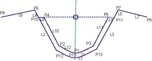
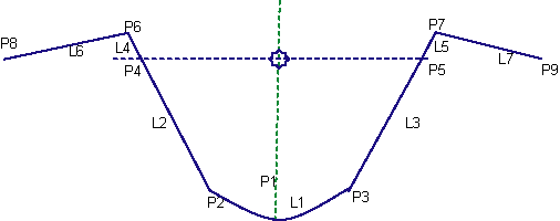
Point, Link, and Shape Codes
The following table lists the point, link, and shape codes for this subassembly that have codes assigned to them. Point, link, or shape codes for this subassembly that do not have codes assigned are not included in this table.
| Point/Link | Codes | Description |
|---|---|---|
| P1 | DrainageChannel_InvertLevel | Middle point of the drainage channel bottom |
| P2,P3 | DrainageChannel_Bottom | |
| P4, P5 | DrainageChannel_Top | |
| P6,P7 | DrainageChannel_Extension | |
| P8,P9 | DrainageChannel_Backslope | |
| P13 | ||
| L1, L2, L3 | Datum, DrainageChannel_Bottom and Top (if lining is NOT used) | |
| L4 to L7 | Datum, Top | |
| L8 to L12 | DrainageChannel_Bottom and TOP (if lining IS used) | |
| S1 | Lining_Material | Drainage Channel Lining Material |
Coding Diagram