This subassembly adds an overlay layer to one side of an existing carriageway, with either a milling or levelling layer added as required.
Attachment
The attachment point is the inside edge point of the overlay layer with finished gradient crossfall.
Input Parameters
Note: All dimensions are in meters or feet unless otherwise noted. All slopes are in run-over-rise form unless indicated as a percent slope with a "%" sign.
| Parameter | Description | Type | Default |
|---|---|---|---|
| Side | Specifies which side of the road centreline to place the rehab subassembly | User defined | Left |
| Design Lane Width same as Existing Lane Width |
|
User defined | No |
| Inside Edge of Existing Lane | This is the start point for calculating existing ground slope | Numeric | 0.000m |
| Outside Edge of Existing lane | This is the start point for calculating existing ground slope | Numeric | 0.000m |
| Overlay Depth | Depth of the overlay layer | Numeric, positive | 0.300m |
| Overlay Slope Options | Specifies overlay slope options.
Tip: Flapping is a term used to describe how the Corrected Crossfall for an overlay in a rehab subassembly is calculated. Flapping outcomes are different, relative to the Slope Tolerance and the Slope Difference between existing ground crossfall and ideal crossfall. If the Slope Difference is less than the Slope Tolerance for the subassembly, then the use case is considered 'within tolerance'. If the Slope Difference is greater than the Slope Tolerance for the subassembly, then the use case is considered 'without tolerance'.
Note: Slope Tolerance is an absolute value. Therefore, for either a Slope Difference of 0.4% or -0.4%, both have an absolute value of 0.4%. If the Slope Tolerance is 0.5%, the 0.4% absolute Slope Difference would be considered within tolerance.
|
User defined | User Defined without Flapping |
| Ideal Crossfall | Specifies user defined ideal crossfall. | Numeric | -2.00% |
| Lane Width | The lane width, determined by the offset of the outside edge of lane from the inside edge of lane. | Numeric | 12.000m |
| Use Profile Options | Select to tie the inside edge of overlay to a profile, adjust level to minimum level depth lock to preceding subassembly.
|
User defined | Minimum Level Depth |
| Minimum Level Depth | Minimum elevation depth between the existing surface and the bottom of the overlay layer. | Numeric | 0.600m |
| Minimum Mill Depth | The minimum mill depth below the existing surface. | Numeric | 0.300m |
| Slope Tolerance | Tolerance for varying the overlay slope. | Numeric | 0.50% |
Output Parameters
| Parameter | Description | Type | Default |
|---|---|---|---|
| Corrected Crossfall | This is the adjusted crossfall for the road, which has been optimised to match, as closely as possible, the rehab subassembly parameters you specified. | Numeric, negative | -2.00% |
| Existing Ground Slope | The crossfall (%) of the existing ground profile, calculated from the inside edge of the lane to the outside edge of the lane. | Numeric, negative | n/a |
Target Parameters
| Parameter | Description | Required? |
|---|---|---|
| Target Surface | Name of the surface defining the existing carriageway | Yes |
| Crown Offset Target | Name of the object defining the offset of the crown point. The following object types can be used as targets for specifying this offset: alignments, polylines, feature lines or survey figures. | No |
| Inside Edge of Lane Offset Target | Name of the object defining the offset of the inside edge of lane. The following object types can be used as targets for specifying this offset: alignments, polylines, feature lines or survey figures. | No |
| Lane Width Target | Name of the object defining the offset of the outside edge of lane. The following object types can be used as targets for specifying this offset: alignments, polylines, feature lines or survey figures. | No |
| Inside Edge of Existing Lane Offset Target | Name of the object defining the inside sample point offset will be used to calculate the existing surface slope. The following object types can be used as targets for specifying this offset: alignments, polylines, feature lines or survey figures. | No |
| Outside Edge of Existing Lane Offset Target | Name of the object defining the outside sample point offset will be used to calculate the existing surface slope. The following object types can be used as targets for specifying this offset: alignments, polylines, feature lines or survey figures. | No |
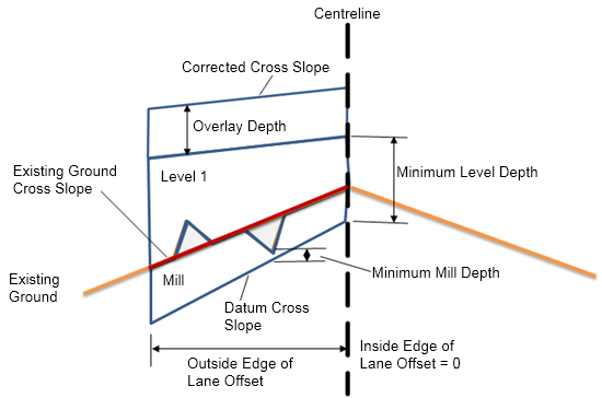
Behaviour
- Areas must be provided for all layers.
- The Levelling area is equal to the areas of Level 1 + Mill layers combined.
- The Milling Area layer is represented in the diagram below as Mill.
- Minimum Level Depth is equal to the area from the top of the milling layer to the bottom of the overlay layer.
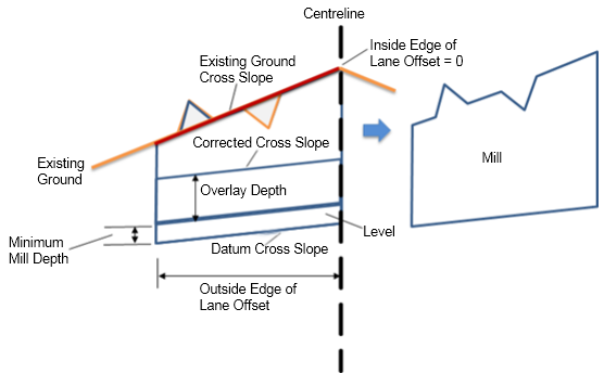
Special Case
When Use Profile is selected in Profile Options, the overlay is located below the existing ground.
- Milling will continue Minimum Mill Depth downwards from bottom of Overlay
- The area of Minimum Mill Depth will be filled as Level area.
- Total Mill area is from the Datum layer to the Existing Ground layer.
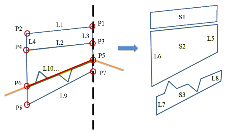
Point, Link and Shape Codes
| Point, Link or Shape | Code | Description |
|---|---|---|
| P1, P2 | EOV | Overlay edges on finished gradient (edges of top of overlay) |
| P3, P4 | EOV_Overlay | Overlay edges beneath levelling layer (edges of bottom of overlay) |
| P7, P8 | EOV_Milling | Overlay edges beneath milling layer (edges of bottom of mill) |
| L1 | Top, Pave | Top of overlay |
| L2, L3, L4 | Overlay | Overlay links |
| L5, L6 | Level | For the levelling case |
| L7, L8 | Mill | For the milling case |
| L9 | Level, Mill, Datum | Links for the milling layer |
| S1 | Overlay | Area between the top and bottom of overlay. This area overlaps the levelling area as shown in the coding diagram below |
| S2 | Level | Area above existing surface and below the bottom of overlay (levelling case) |
| S3 | Mill | Area between bottom of existing surface and bottom of mill (milling case) |