This subassembly inserts links for a constant-slope raised central reserve between two points.
Use the MarkPoint subassembly first if the connecting point has not already been marked.
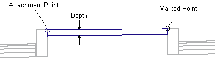
Attachment
The attachment point may be at either edge of the central reserve finished surface. The marked point must be at the opposite edge.
Input Parameters
Note: Subbase dimensions are in meters or feet. Kerb-and-channel dimensions must be given in millimeters or inches.
|
Parameter |
Description |
Type |
Default |
|---|---|---|---|
|
Marked Point |
Name of the marked point on the central reserve edge opposite the attachment point |
String |
None |
|
Depth |
Depth of the central reserve cap. May be zero for an unpaved central reserve |
Numeric, positive |
0.100 m 0.333 ft |
Target Parameters
This section lists the parameters in this subassembly that can be mapped to one or more target objects, such as a surface, alignment, or profile object in a drawing. For more information, see To Specify Corridor Targets.
Target Parameters: None.
Output Parameters
None.
Behavior
The top of central reserve link is inserted between the attachment point and marked point. If a non-zero Depth is given, the bottom of central reserve link is inserted parallel to the top, and vertical links are added to close the shape.
Superelevation Axis of Rotation Support
This subassembly works with all axis of rotation pivot methods.
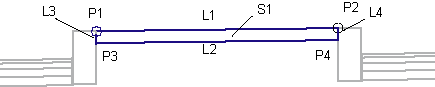
Point, Link, and Shape Codes
The following table lists the point, link, and shape codes for this subassembly that have codes assigned to them. Point, link, or shape codes for this subassembly that do not have codes assigned are not included in this table.
|
Point, Link, or Shape |
Code |
Description |
|---|---|---|
|
P1, P2 |
None |
Edges of central reserve on finish surface |
|
P3, P4 |
||
|
L1 |
Top |
Top of central reserve |
|
L2 |
Datum |
Bottom of central reserve |
|
L3, L4 |
None |
|
|
S1 |
Central Reserve |
Layout Mode Operation
In layout mode, this subassembly shows the generic layout mode display.
Coding Diagram