This subassembly inserts a travel lane, applying the Outside Lane superelevation slope value, and widens the pavement at superelevated regions.
It can be used for most undivided roads, or divided roads with no lane slope break on either side. It may also be used for the outside lanes of divided crowned or broken-back highways. The pavement structure follows the standards described in “Pavement Structure on Paved Sections” in the AutoCAD Civil 3D Help. The only difference between this subassembly and the LaneOutsideSuper subassembly is that this subassembly also widens the pavement width in superelevated regions of the corridor.
Attachment
The attachment point is (a) at the inside edge of lane on finished gradient, if the insertion point is Crown, or (b) at the outside edge of travel way,if the insertion point is at the edge of travel way. This component can be attached to either the left or right side.
Input Parameters
Note: All dimensions are in meters or feet unless otherwise noted. All slopes are in run-over-rise form (for example, 4 : 1) unless indicated as a percent slope with a “%” sign.
|
Parameter |
Description |
Type |
Default |
|---|---|---|---|
|
Side |
Specifies which side to place the subassembly. |
Left / Right |
Right |
|
Insertion Point |
Specifies insertion point of the lane either at the crown, or at the edge of travel way |
List of options: (a) Crown, (b) Edge of Travel Way |
Crown |
|
Crown Point on Inside |
Specifies that the inside edge of travelway be coded as Crown |
Yes / No |
No |
|
Width |
Width of the lane from the offset of the inside edge to the offset of the outside edge |
Numeric, positive |
3.6 m 12.0 ft |
|
Default %Slope |
Default % slope of the lane to be used when the superelevation slope for the alignment is not defined |
Numeric |
-2.0 |
|
Pave1 Depth |
Thickness of the Pave1 layer (zero to omit) |
Numeric, non-negative |
0.025 m 0.083 ft |
|
Pave2 Depth |
Thickness of the Pave2 layer (zero to omit) |
Numeric, non-negative |
0.025 m 0.083 ft |
|
Base Depth |
Thickness of the base layer (zero to omit) |
Numeric, non-negative |
0.100 m 0.333 ft |
|
Subbase Depth |
Thickness of the subbase layer (zero to omit) |
Numeric, non-negative |
0.300 m 1.0 ft |
|
Wheelbase Length |
Length of the vehicle wheelbase, including front overhang |
Numeric, positive |
10 m 33 ft |
|
Number of Travel Lanes |
Number of planned travel lanes in this subassembly |
Integer, positive |
1 |
Target Parameters
This section lists the parameters in this subassembly that can be mapped to one or more target objects. For more information, see To Specify Corridor Targets.
|
Parameter |
Description |
Status |
|---|---|---|
|
Width |
May be used to override the fixed lane Width and tie the edge-of-lane to an offset alignment. The following object types can be used as targets for specifying the width: alignments, polylines, feature lines, or survey figures. |
Optional |
|
Outside Level |
May be used to override the normal lane slope and tie the outer edge of the travel lane to the level of a profile. The following object types can be used as targets for specifying the level: profiles, 3D polylines, feature lines, or survey figures. |
Optional |
Output Parameters
|
Parameter |
Description |
Type |
|---|---|---|
|
Lane Width |
Width of the lane |
Numeric |
|
Lane %Slope |
% slope of the lane |
Numeric |
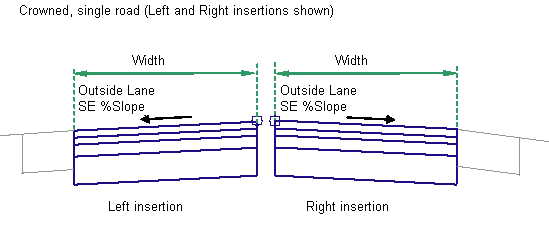
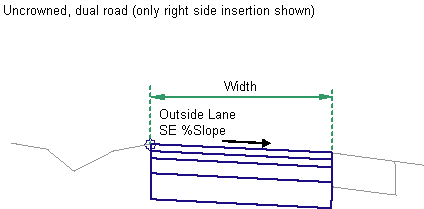
Behavior
The Outside Lane superelevation slope is obtained from the superelevation specifications for the baseline alignment. Starting at the attachment point, a finish surface and parallel subgradient are inserted using the given width, depth, and the superelevation slope. Vertical links close the shape at either end of the lane.
Lane Widening
If the current chainage is within a superelevated region, then the lane width value is calculated as follows:
Width = Default Width + Pavement Widening
where Pavement Widening =
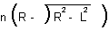
n = Number of lanes
R = Radius of the alignment at full superelevation
L = Length of wheelbase including the front overhang
The lane should be widened starting from the "End Normal Crossfall" and by the time "full super" chainage lane should be "default width + pavement widening". If transitions are used, typically this widening transition length is equal to the length of the transition.
The key steps in completing this conditional subassembly are:
- Set pavement widening to zero.
- Get the default width from parameters.
- Verify whether a chainage is in Superelevation zone or not.
- If Yes, then find the radius of curvature at full super chainage (not current chainage).
- Compute the pavement widening value from the equation mentioned in the spec (ExtraW).
- Find out the chainage value of “End Normal Crossfall” in this region; and similarly find chainage value of “Full Super”; find the difference as length along alignment to distribute (L).
- Divide ExtraW by L and get that factor RateW.
- For the current chainage, find the difference between “end normal crossfall” chainage and current chainage (DeltaL).
- Multiply RateW by DeltaL to get DeltaW for the current chainage.
- Add the DeltaW to the default Width provided in the subassembly properties.
- Hence, the new width at the current chainage is = Width+DeltaW.
The DeltaW is the only parameter (note that it is not an input parameter) that is shown in the following diagram.
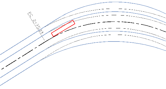
The preceding diagram is not accurate, but indicative. The black line represents centerline and the blue lines on left and right denotes edges of different lanes on right and left sides (after design). The light (gray) colored lines in the diagram indicate original right and left edges. The deviation of the designed edges is due to the provision of extra widening.
If an offset horizontal alignment name is assigned to the Width during corridor modeling, the width of the lane will vary to match the offset of the alignment.
Superelevation Axis of Rotation Support
This subassembly can be used with superelevation axis of rotation pivot points only in cases when the parent assembly is built out from the baseline.
Layout Mode Operation
In layout mode, this subassembly displays all lane links using the width and depth input parameters at a -2% slope.
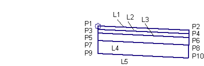
Point, Link, and Shape Codes
The following table lists the point, link, and shape codes for this subassembly that have codes assigned to them. Point, link, or shape codes for this subassembly that do not have codes assigned are not included in this table.
|
Point, Link, or Shape |
Code |
Description |
|---|---|---|
|
P2 |
EC |
Inside edge of lane on finish surface |
|
P4 |
EC_Pave1 |
Inside edge of lane on Pave1. |
|
P6 |
EC_Pave2 |
Inside edge of lane on Pave2 |
|
P8 |
EC_Base |
Inside edge of lane on Base |
|
P10 |
EC_Sub |
Inside edge of lane on Subbase |
|
L1 |
Top, Pave |
Finish surface |
|
L2 |
Pave1 |
Pave1 surface |
|
L3 |
Pave2 |
Pave2 surface |
|
L4 |
Base |
Base surface |
|
L5 |
SubBase |
Subbase surface |
|
S1 |
Pave1 |
Area between finish surface and Pave1 |
|
S2 |
Pave2 |
Area between Pave1 and Pave2 |
|
S3 |
Base |
Area between Pave2 and Base |
|
S4 |
SubBase |
Area between Base and Subbase |
Coding Diagram