This subassembly inserts surfaces to define a flush central reserve with an optional New Jersey Barrier.
The pavement structure follows the standards described in “Pavement Structure of Paved Sections" in the AutoCAD Civil 3D Help.
Attachment
The attachment point is at the center of central reserve on the finish surface surface. This component inserts to the left and right side simultaneously.
Input Parameters
Note: All dimensions are in meters or feet unless otherwise noted. All slopes are in run-over-rise form (for example, 4 : 1) unless indicated as a percent slope with a “%” sign.
|
Parameter |
Description |
Type |
Default |
|---|---|---|---|
|
Left Slope |
Slope of the left central reserve surface |
Selection list |
-2 % |
|
Right Slope |
Slope of the right central reserve surface |
Selection list |
-2 % |
|
Include Barrier |
True shows the New Jersey barrier. False omits the barrier. |
Selection list |
Include Barrier |
|
Left Width |
Width from the central reserve centerline to the left edge of central reserve |
Numeric, positive |
1.2 m 4.0 ft |
|
Right Width |
Width from the central reserve centerline to the right edge of central reserve |
Numeric, positive |
1.2 m 4.0 ft |
|
Left Lane - Use Superelevation |
Specifies to use superelevation slope for the left lane |
Selection list:
|
Yes |
|
Default Left Slope |
Specifies the default slope of the left lane, if superelevation slope is not specified | Numeric |
- 2 % |
|
Right Lane - Use Superelevation |
Specifies to use superelevation slope for the right lane. |
Selection list:
|
Yes |
|
Default Right Slope |
Specifies the default slope of the right lane, if superelevation slope is not specified | Numeric |
- 2 % |
| Shoulder Slope Direction | Specifies whether the shoulder slopes away from the crown or towards the crown |
Selection List:
|
Away from Crown |
|
Pave1 Depth |
Thickness of the Pave1 layer; zero to omit |
Numeric, positive |
0.025m 0.083 ft |
|
Pave2 Depth |
Thickness of the Pave2 layer; zero to omit. |
Numeric, positive |
0.025 m 0.083 ft |
|
Base Depth |
Thickness of the base layer |
Numeric, positive |
0.100 m 0.333 ft |
|
Subbase Depth |
Thickness of the subbase layer |
Numeric, positive |
0.300 m 1.0 ft |
|
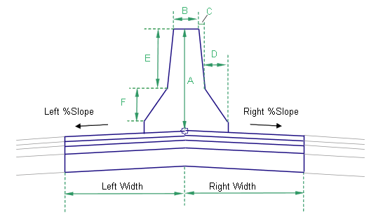
Dimension A (mm or inches) |
Height of the barrier at the center of central reserve |
Numeric, positive |
810 mm 32 in |
|
Dimension B (mm or inches) |
As shown in diagram |
Numeric, positive |
232 9 in |
|
Dimension C (mm or inches) |
As shown in diagram |
Numeric, positive |
59 mm 2 in |
|
Dimension D (mm or inches) |
As shown in diagram |
Numeric, positive |
125 mm 5 in |
|
Dimension E (mm or inches) |
As shown in diagram |
Numeric, positive |
557 mm 22 in |
|
Dimension F (mm or inches) |
As shown in diagram |
Numeric, positive |
178 mm 7 in |
Target Parameters
This section lists the parameters in this subassembly that can be mapped to one or more target objects, such as a surface, alignment, or profile object in a drawing. For more information, see To Specify Corridor Targets.
|
Parameter |
Description |
Status |
|---|---|---|
|
Left Width |
May be used to override the fixed Left Width and tie the left edge-of-central reserve to an offset alignment. The following object types can be used as targets for specifying this offset: alignments, polylines, feature lines, or survey figures. |
Optional |
|
Right Width |
May be used to override the fixed Right Width and tie the right edge-of-central reserve to an offset alignment. The following object types can be used as targets for specifying this offset: alignments, polylines, feature lines, or survey figures. |
Optional |
Output Parameters
|
Parameter |
Description |
Type |
|---|---|---|
|
Superelevation Axis of Rotation |
Indicates whether the subassembly supports the axis of rotation calculation. To view a description of the parameter, in the Properties window, hover the cursor over the parameter. For more information, see Profile Gradient Line Adjustments During Superelevation. |
Static (Description) |
|
Left %Slope |
% slope of the left side of the central reserve |
Numeric |
|
Right %Slope |
% slope of the right side of the central reserve |
Numeric |
Behavior
The pavement structure links are inserted outward left and right of the attachment point for the given widths and slopes. If the Include Barrier value is True, a New Jersey barrier is inserted symmetrically about the central reserve centerline. If alignments are given as target parameters for the Left and Right Widths, the widths are adjusted to tie to the alignment offsets at each chainage along the corridor.
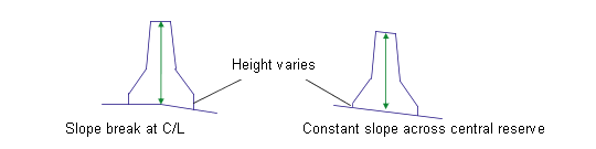
If the central reserve is in superelevation with a single constant slope across the entire central reserve, the top of the barrier is slanted to match the central reserve slope. Otherwise the top of the barrier remains horizontal. In all cases, the barrier height (Dimension A) is held constant at the centerline of the barrier.
Superelevation Axis of Rotation Support
This subassembly works only with Carriageway Types that have a Pivot Method of Central Reserve Edges and a Central Reserve Treatment of Maintain Central Reserve Shape. If you use this subassembly with any other Pivot Method or with Distorted Central Reserve Treatment, it will produce a result equivalent to Central Reserve Edges with Maintain Central Reserve Shape.
Layout Mode Operation
In layout mode, this subasssembly displays all pavement links using the width and depth input parameters at a -2% slope. If Include Barrier is True, the barrier is displayed with the given dimensions.
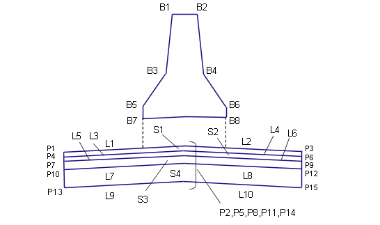
Point, Link, and Shape Codes
The following table lists the point, link, and shape codes for this subassembly that have codes assigned to them. Point, link, or shape codes for this subassembly that do not have codes assigned are not included in this table.
|
Point, Link, or Shape |
Code |
Description |
|---|---|---|
|
All barrier points |
Barrier |
All points on the concrete barrier |
|
P1, P3 |
EC |
Inside edge of lane on finish surface |
|
P2 |
Crown |
Crown of central reserve on finish surface |
|
P4, P6 |
EC_Pave1 |
Edge of carriageway on Pave1 |
|
P5 |
Crown_Pave1 |
Crown on Pave1 |
|
P7, P9 |
EC_Pave2 |
Edge of carriageway on Pave2 |
|
P8 |
Crown_Pave2 |
Crown on Pave2 |
|
P10, P12 |
EC_Base |
Edge of carriageway on Base |
|
P11 |
Crown_Base |
Crown on Base |
|
P13, P15 |
EC_Sub |
Edge of carriageway on Subbase |
|
P14 |
Crown_Sub |
Crown on Subbase |
|
L1, L2 |
Top, Pave |
|
|
L3, L4 |
Pave1 |
|
|
L5, L6 |
Pave2 |
|
|
L7, L8 |
Base |
|
|
L9, L10 |
SubBase Datum |
|
|
All barrier links |
Barrier |
|
|
S1 |
Pave1 |
Area between finish surface and Pave1 |
|
S2 |
Pave2 |
Area between Pave1 and Pave2 |
|
S3 |
Base |
Area between Pave2 and Base |
|
S4 |
SubBase |
Area between Base and Subbase |
|
S5 |
Barrier |
Shape inclosed by the barrier. |
Coding Diagram