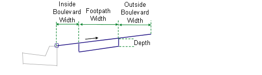
This subassembly inserts links for a concrete footpath with inside and outside grass boulevards.
Attachment
The attachment point is at the inside edge of the inside boulevard. The UrbanFootpath subassembly is typically attached to a back-of-kerb or edge of pavement.
Input Parameters
Note: All dimensions are in meters or feet unless otherwise noted. All slopes are in run-over-rise form (for example, 4 : 1) unless indicated as a percent slope with a “%” sign.
|
Parameter |
Description |
Type |
Default |
|---|---|---|---|
|
Side |
Specifies to insert the subassembly either on the right or the left side of the attachment point. |
Left/Right |
Right |
|
Inside Boulevard Width |
Width of the inside grass boulevard |
Numeric, positive |
0.0 |
|
Footpath Width |
Width of the concrete footpath |
Numeric, positive, non-zero |
1.5 m 5.0 ft |
|
Outside Boulevard Width |
Width of the outside grass boulevard |
Numeric, positive |
0.0 |
|
%Slope |
% slope of the footpath and grass strips. Positive slopes are upwards from the attachment point. |
Numeric |
2 (%) |
|
Depth |
Depth of concrete for the footpath |
Numeric, positive |
0.100 m 0.333 ft |
Behavior
The inside grass strip, footpath, and outside grass boulevard links are inserted outward from the attachment point at the given slope. The grass strips can be omitted by specifying a zero-width.
Optionally, various element widths can be attained by attaching to offset alignments. Also, the footpath crossfall can be derived by tying into an offset profile.
Target Parameters
This section lists the parameters in this subassembly that can be mapped to one or more target objects, such as a surface, alignment, or profile object in a drawing. For more information, see To Specify Corridor Targets.
|
Parameter |
Type of Assignment |
Status |
|---|---|---|
|
Inside Boulevard Width |
May be used to override the fixed Inside Boulevard Width and tie the inside edge-of-footpath to an offset alignment. The following object types can be used as targets for specifying this offset: alignments, polylines, features lines, or survey figures. |
Optional |
|
Footpath Width |
May be used to override the fixed Width of Footpath and tie the outside edge-of-footpath to an offset alignment. The following object types can be used as targets for specifying this offset: alignments, polylines, features lines, or survey figures. |
Optional |
|
Outside Boulevard Width |
May be used to override the fixed Outside Boulevard Width with an offset alignment. The following object types can be used as targets for specifying this offset: alignments, polylines, features lines, or survey figures. |
Optional |
Output Parameters
None.
Layout Mode Operation
In layout mode, this subassembly displays the boulevards and footpath based on the input parameter values given.
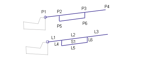
Point, Link, and Shape Codes
|
Point / Link |
Code |
Description |
|---|---|---|
|
P2 |
Footpath_In |
Inside edge of footpath on finish surface |
|
P3 |
Footpath_Out |
Outside edge of footpath on finish surface |
|
L1 |
Top Sod Datum |
|
|
L2 |
Top Footpath |
|
|
L3 |
Top Sod Datum |
|
|
L4 – L6 |
Footpath Datum |
|
|
S1 |
Footpath |
Footpath concrete area |
Coding Diagram