This subassembly inserts links for a standard shape concrete kerb-and-channel with subbase.
User-defined input parameters control the dimensions of the shape.
Attachment
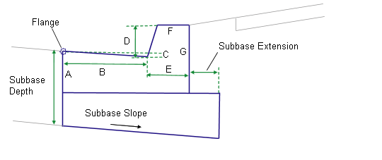
The attachment point is at the flange point of the channel or the back of the kerb.
Input Parameters
Note: Subbase dimensions are in meters or feet. Kerb-and-channel dimensions must be given in millimeters or inches.
|
Parameter |
Description |
Type |
Default |
|---|---|---|---|
|
Side |
Specifies to insert the subassembly either on the right or the left side of the attachment point. |
Left/Right |
Right |
|
Insertion Point |
Specifies insertion point of the kerb and channel as either Channel Edge or Back of Kerb |
Boolean |
Channel Edge |
|
Channel Slope Method |
Specifies method of channel slope input |
Selection list |
Outside Lane Slope |
|
Channel Slope |
Specifies fixed channel slope |
Numeric |
- 2% |
| Channel Slope Direction | Specifies whether the channel slopes towards the crown or away from the crown | Selection list | Away from Crown |
|
Subbase Depth |
Depth to subbase at the flange point. Use zero if there is no subbase. |
Numeric, positive |
0.450 m 1.5 ft |
|
Subbase Extension |
Distance the subbase is extended beyond the back-of-kerb. Use zero to terminate the subbase at the back-of-kerb. |
Numeric, positive |
0.3 m 1.0 ft |
|
Subbase Slope Method |
Selects whether to use the Outside Lane superelevation slope for the subbase layer, or to set a numeric % slope value |
Selection list |
Outside Lane Slope |
|
Subbase %Slope |
% slope of the subbase layer. Not used if Use SE is set to True. |
Numeric |
-2 (%) |
|
Dimension A (mm/in) |
Depth of the channel at the flange point |
Numeric, positive, non-zero |
175 mm 7 in |
|
Dimension B (mm/in) |
Width from the flange point to the channel invert level |
400 mm 16 in |
|
|
Dimension C (mm/in) |
Depth from the flange point to the channel invert level |
Numeric, positive, non-zero |
25 mm 1 in |
|
Dimension D (mm/in) |
Height of kerb from the channel invert level to the top-of-kerb |
Numeric, positive, non-zero |
150 mm 6 in |
|
Dimension E (mm/in) |
Width from the channel invert level to the back-of-kerb |
Numeric, positive, non-zero |
200 mm 8 in |
|
Dimension F (mm/in) |
Width of the top-of-kerb |
Numeric, positive, non-zero |
150 mm 6 in |
|
Dimension G (mm/in) |
Height of the back-of-kerb |
Numeric, positive, non-zero |
325 mm 13 in |
Behavior
The kerb and channel links are inserted based on the Input Parameter dimensions Dimension A – Dimension F. All dimensions must be positive, non-zero values. If a non-zero subbase depth is given, the subbase layer is inserted to the back of kerb, and continues for the Subbase Extension width. The subbase layer closes to the bottom-back-of-kerb, as shown in the diagram.
The subassembly builds the shape for a simple kerb and channel, with the attachment point either at (a) inside edge of the channel (or lip), or (b) the back of the kerb. The face of the kerb is given a small, constant width to make it non-vertical.
Target Parameters
This section lists the parameters in this subassembly that can be mapped to one or more target objects, such as a surface, alignment, or profile object in a drawing. For more information, see To Specify Corridor Targets.
Target Parameters: None.
Output Parameters
| Parameter | Description | Type |
|---|---|---|
|
Superelevation Axis of Rotation |
Indicates whether the subassembly supports the axis of rotation calculation. To view a description of the parameter, in the Properties window, hover the cursor over the parameter. For more information, see Profile Gradient Line Adjustments During Superelevation. |
Static (Description) |
Superelevation Axis of Rotation Support
If the Channel Slope Direction is set to Away from Crown, then the channel slope is the opposite of the superelevation slope. If Channel Slope Direction is set to Towards Crown, the channel slope is reversed.
Layout Mode Operation
In layout mode, this subassembly displays the kerb-and-channel component based on the input parameters given. If the Use SE parameter is set to true, the subbase layer is inserted at a slope of -2%.
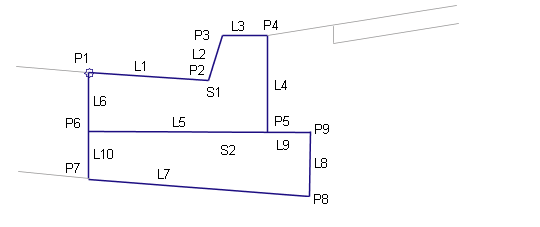
Point, Link, and Shape Codes
The following table lists the point, link, and shape codes for this subassembly that have codes assigned to them. Point, link, or shape codes for this subassembly that do not have codes assigned are not included in this table.
|
Point / Link |
Code |
Description |
|---|---|---|
|
P1 |
Flange |
Flange point of the channel |
|
P2 |
InvertLevel_Channel |
Channel invert level point |
|
P3 |
TopKerb |
Top-of-kerb |
|
P4 |
BackKerb |
Back-of-kerb |
|
L1 – L3 |
Top, Kerb |
Finish surface on the kerb and channel |
|
L7 |
SubBase Datum |
|
|
S1 |
Kerb |
Kerb-and-channel concrete area |
|
S2 |
SubBase |
Coding Diagram