This subassembly is used to grade plots from a highway boundary line.
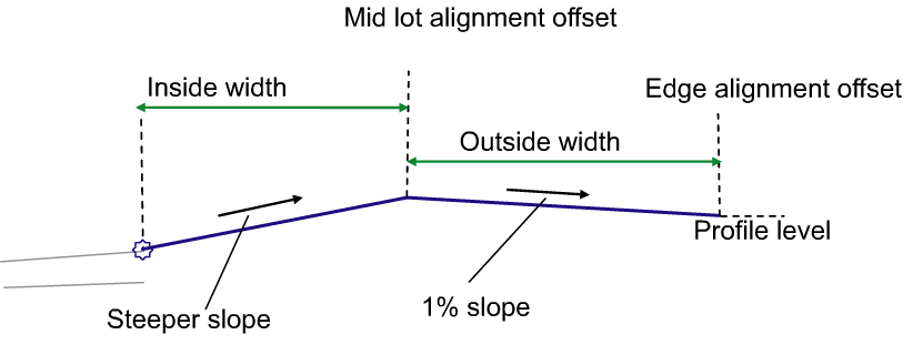
The following illustration shows an example of this subassembly being used when the target profile level at the back of the plot is higher than the attachment point.
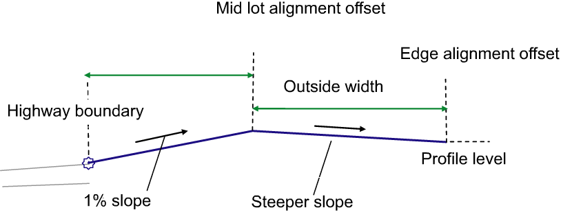
The following illustration shows an example of this subassembly being used when the attachment point is higher than the target profile level at the back of the plot.
Attachment
The attachment point is at the inside edge of the lane on the finished surface.
Input Parameters
Note: All dimensions are in meters or feet unless otherwise noted. All slopes are in run-over-rise form (for example, 4 : 1) unless indicated as a percent slope with a “%” sign.
|
Parameter |
Description |
Type |
Default |
|---|---|---|---|
|
Side |
Indicates which side the subassembly is inserted towards. |
Left \ Right |
Right |
|
Inside Width |
The inside width of the plot. |
Numeric, positive |
3.6 m 12.0 ft |
|
Outside Width |
The outside width of the plot. |
Numeric, positive |
3.6 m 12.0 ft |
|
Min Slope |
The minimum slope for the outside width of the plot. |
Numeric, positive |
1 % |
Target Parameters
This section lists the parameters in this subassembly that can be mapped to one or more target objects, such as a surface, alignment, or profile object in a drawing. For more information, see To Specify Corridor Targets.
|
Parameter |
Description |
Status |
|---|---|---|
|
Middle Offset |
May be used to override the fixed Inside Width by tying the mid plot line to an offset alignment. The following object types can be used as targets for specifying this offset: alignments, polylines, feature lines, or survey figures. |
Optional |
|
Edge Offset |
May be used to override the fixed Outside Width by tying end plot line to an offset alignment. The following object types can be used as targets for specifying this offset: alignments, polylines, feature lines, or survey figures. |
Optional |
|
Edge Level |
May be used to override the fixed Level by tying end plot line to a level. The following object types can be used as targets for specifying this level: profiles, 3D polylines, feature lines, or survey figures. |
Required |
Output Parameters
None.
Behavior
The plot gradient assembly tool needs to start at the highway boundary and, much like the BasicLaneTransition subassembly, it will hold gradient and change offset to the middle of the plot at a default slope of 1%. The value of the slope can be input by the user. At the middle of the plot will be an alignment with no profile. So the assembly will be a link from highway boundary to that mid plot alignment at 1% slope. Then the mid plot alignment will link to the back of plot, which is a fixed level; for example, 74.00 feet. We need to maintain a minimum slope of 1% on the back half of the plot as well. Therefore there needs to be a rule in place if the front of the plot gradient at 1% slope does not allow for a minimum slope of 1% for the back half of the plot, then the back half of the plot gradient needs to change to 1% and the front half plot gradient needs to go steeper.
Layout Mode Operation
In layout mode, this subassembly draws the lane using the input parameter values. It will use 1% as the steeper slope value.
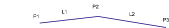
Point, Link, and Shape Codes
The following table lists the point, link, and shape codes for this subassembly that have codes assigned to them. Point, link, or shape codes for this subassembly that do not have codes assigned are not included in this table.
|
Point, Link, or Shape |
Code |
Description |
|---|---|---|
|
P1 |
Crown |
Crown of road on finished surface. |
|
P2 |
Hinge |
Plot hinge point. |
|
L1, L2 |
Top |
Finish surface. |
Coding Diagram