This subassembly is used to replace an existing kerb and channel, with the sod strip tying to the existing inside edge of footpath. The vertical placement of kerb and channel is determined by allowable milling and/or overlay at the flange points and by allowable ranges of slopes for sod strip.
To apply this subassembly, flange point information (alignment or offset value) is essential.
Attachment
The attachment point is outside/highside point of the sod strip edge of the footpath. Though notionally this attachment point is to mark the highside of the sod strip, actual location of sod strip high point could vary from this as the user attaches an appropriate marked point or alignment and profile. Therefore, this attachment point is more of layout time assistance rather than design point control.
Input Parameters
Note: All dimensions are in meters or feet unless otherwise noted. All slopes are in run over rise form (for example, 4 : 1) unless indicated as a percent slope with a "%" sign.
|
Parameter |
Description |
Type |
Default |
|---|---|---|---|
|
Side |
Specifies to insert the subassembly either on the right or the left side of the attachment point. |
Left/Right |
Right |
|
Flange Point Offset from CL |
Point defining the offset of the face of the flange of the channel. This offset is as measured from the baseline point. |
Numeric |
3.6 m 10 ft |
|
Footpath Point |
This inside footpath point will be used as the high point of sod strip. (OPTIONAL) |
String |
None |
|
Max Milling |
Maximum allowable depth of the flange point below the edge of existing pavement. | Numeric, positive |
0.05 m 2.5 in |
|
Desirable Lift |
Desirable difference in level from the edge of existing pavement to the flange point. A positive value is for the flange point being above the existing pavement. |
Numeric, positive |
0.08m 3.5 in |
| Min Sod Slope | Minimum allowable slope from the back of kerb to the footpath point. |
0.02 |
|
|
Max Sod Slope |
Maximum allowable slope from the back of kerb to the footpath point. |
0.06 |
|
|
Mark Inside Point |
Mark Flange Point - name of a marked point to be stored at the flange point - for later rehab subassemblies. | String |
None |
| The following are the same parameters as KerbAndChannelGeneral subassembly. | |||
|
Subbase Depth |
Depth to subbase at the flange point. Use zero if there is no subbase. |
Numeric, positive |
0.450 m 1.5 ft |
|
Subbase Extension |
Distance the subbase is extended beyond the back-of-kerb. Use zero to terminate the subbase at the back-of-kerb. |
Numeric, positive |
0.3 m 1 ft |
|
Subbase Slope Method |
Selects whether to use the Outside Lane superelevation slope for the subbase layer, or to set a numeric % slope value |
Selection list |
Fixed Slope |
|
Subbase %Slope |
% slope of the subbase layer. Not used if Use SE is set to True. |
Numeric |
-2 (%) |
|
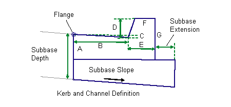
Dimension A (mm/in) |
Depth of the channel at the flange point. |
Numeric, positive, non-zero |
175 mm 6 in |
|
Dimension B (mm/in) |
Width from the flange point to the channel invert level. |
400 mm 16 in |
|
|
Dimension C (mm/in) |
Depth from the flange point to the channel invert level. |
Numeric, positive, non-zero |
25 mm 1 in |
|
Dimension D (mm/in) |
Height of kerb from the channel invert level to the top-of-kerb. |
Numeric, positive, non-zero |
150 mm 6 in |
|
Dimension E (mm/in) |
Width from the channel invert level to the back-of-kerb. |
Numeric, positive, non-zero |
200 mm 8 in |
|
Dimension F (mm/in) |
Width of the top-of-kerb. |
Numeric, positive, non-zero |
150 mm 6 in |
|
Dimension G (mm/in) |
Height of the back-of-kerb. |
Numeric, positive, non-zero |
325 mm 13 in |
Target Parameters
This section lists the parameters in this subassembly that can be mapped to one or more target objects, such as a surface, alignment, or profile object in a drawing. For more information, see To Specify Corridor Targets.
|
Parameter |
Description |
Status |
|---|---|---|
| Inside Edge of Footpath | This will set the offset value for the highside point for sod strip. The following object types can be used as targets for specifying this offset: alignments, polylines, features lines, or survey figures. |
Optional |
| Flange Point | This will establish the offset value of flange point to start the subassembly. The following object types can be used as targets for specifying this offset: alignments, polylines, features lines, or survey figures. |
Optional |
| Inside Edge of Footpath Profile | This will set the offset value for the highside point for sod strip. The following object types can be used as targets for specifying this level: profiles, 3D polylines, feature lines, or survey figures. |
Optional |
| EGTopSurf | Name of the existing surface, used to determine the edge of pavement level at the flange point, and is also used to determine the level of the Footpath Point if given as an offset or alignment; but profiles not set. The following object types can be used as targets for specifying this surfaces: surfaces. |
Required |
If marked points are provided, target parameters are unnecessary and will be ignored even if set. If marked points are not set and offsets or alignments are used to locate points, it is expected to set profiles through target parameters. If they are not, this subassembly takes its level from the surface set in the target parameter listed above.
Output Parameters
|
Parameter |
Description |
Type |
Default |
|---|---|---|---|
|
Superelevation Axis of Rotation |
Indicates whether the subassembly supports the axis of rotation calculation. To view a description of the parameter, in the Properties window, hover the cursor over the parameter. For more information, see Profile Gradient Line Adjustments During Superelevation. |
Static (Description) |
|
|
Sod Strip Slope |
Crossfall of designed sod strip | Numeric | |
|
Channel Slope |
Channel slope in the new kerb and channel subassembly |
Numeric, positive |
Behavior
This subassembly is used to place a new kerb and channel parametrically, and can optionally tie (with a sod strip) into either the inside edge of the existing footpath, or to a new footpath created with another subasembly. The horizontal placement of the kerb and channel is determined from the previously known flange point location. Highside of the sod strip can be located either by a fixed offset or any other marked point, such as the inside edge of footpath. Alternatively, this point can come from target parameters of an aligment and profile. Newly designed flange point, optionally marked so that it can be used as input later for replacement lane subassemblies.
Key steps in completing this conditional subassembly are as follows:
- Get existing pavement level at the flange point offset.
- Set flange point level based on the minimum lift value.
- Next insert kerb and channel points from P to P4 using the input parameters (similar to KerbAndChannelGeneral).
- If the inside footpath marked point is assigned, establish that point as P10. If marked point is not associated, look for target parameters for 'inside edge of footpath" alignment. If yes, then get profile level from the surface target parameter.
- If none of the above data is available for the highside of the sod strip, use the offset as dictated by attachment point to establish point P10.
- Find the slope between P4 and P10.
- Check whether that slope is within the parameters of Min/Max sod strip slopes.
- If it is lower than minimum, set the slope to minimum allowable and computed points P4 to P1 backwards. Similarly, if the slope is more than maximum allowable sod strip slopes, set it to maximum allowable and calculate P4 to P1.
- Check whether the level difference between P1 and P11 is within tolerable limits of max milling. If P is below P11 and difference is more than max milling, then abort, resulting in an error displayed in the event viewer.
All other kerb and channel links are inserted, based on the Input Parameter dimensions Dimension A - Dimension F. All dimensions must be positive, non-zero values. If a non-zero subbase depth is given, the subbase layer is inserted to the back of kerb, and continues for the Subbase Extension width. The subbase layer closes to the bottom-back-of-kerb as shown in the diagram.
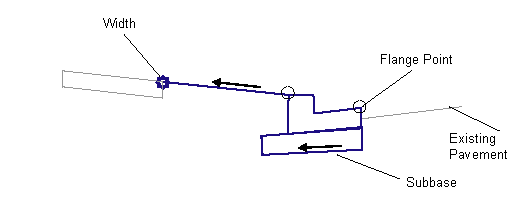
Layout Mode Operation
In layout mode , this subassembly is set based on the attachment point and the default flange point offset from baseline. The width of the sod strip is computed by subtracting the kerb and channel total widt from "flange point to attacment point" distance. The minimum allowable sod strip slope is used to calculate the back of kerb point from which the rest of the kerb and channel is drawn, using the input parameters given.
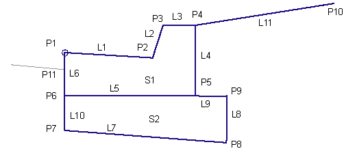
Point, Link, and Shape Codes
The following table lists the point, link, and shape codes for this subassembly that have codes assigned to them. Point, link, or shape codes for this subassembly that do not have codes assigned are not included in this table.
|
Point / Link |
Code |
Description |
|---|---|---|
|
P1 |
Flange |
Flange point of the channel |
|
P2 |
InvertLevel_Channel |
Channel invert level point |
|
P3 |
TopKerb |
Top-of-kerb |
|
P4 |
BackKerb |
Back-of-kerb |
|
L1–L6 |
Kerb |
All kerb links |
|
L1 – L3 |
Top |
Finish surface on the kerb and channel |
|
L7 |
SubBase Datum |
|
|
L4, L8, L9 |
Datum |
|
|
L11 |
Top, Datum, Sod |
|
|
S1 |
Kerb |
Kerb-and-channel concrete area |
|
S2 |
SubBase |
Coding Diagram