This subassembly creates a a simple kerb and channel structure at the inside or outside edges of carriageway.
Attachment
The attachment point is at the flange point of the channel or back of the kerb.
Input Parameters
Note: All dimensions are in meters or feet unless otherwise noted. All slopes are in run-over-rise form (for example, 4 : 1) unless indicated as a percent slope with a “%” sign.
|
Parameter |
Description |
Type |
Default |
|---|---|---|---|
|
Side |
Specifies which side to place the subassembly. |
Left / Right |
Right |
|
Insertion Point |
Specifies insertion point of the kerb and channel as either Channel Edge or Back of Kerb |
Boolean |
Channel Edge |
|
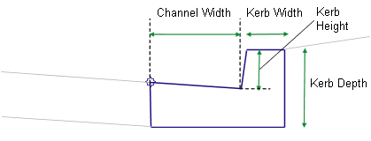
Channel Width |
Width from the flange of the channel to the invert level |
Numeric, positive |
0.45 m 1.5 ft |
|
Channel %Slope |
% slope of the channel |
Numeric |
-6% |
|
Kerb Height |
Height from the invert level to the top of kerb |
Numeric, positive |
0.225 m 0.75 ft |
|
Kerb Width |
Width of the top of kerb |
Numeric, positive |
0.15 m 0.5 ft |
|
Kerb Depth |
Depth from the top of kerb to the bottom of kerb at the back-of-kerb point |
Numeric, positive |
0.45 m 1.5 ft |
Target Parameters
This section lists the parameters in this subassembly that can be mapped to one or more target objects. For more information, see To Specify Corridor Targets.
Target Parameters: None.
Output Parameters
None.
Behavior
The subassembly builds the shape for a simple kerb and channel with the attachment point either at (a) the inside edge of the channel (or lip), or (b) the back of the kerb. The face of the kerb is given a small, constant width to make it non-vertical.
Layout Mode Operation
In layout mode, this subassembly draws the kerb and channel shape as specified by the input parameter values.
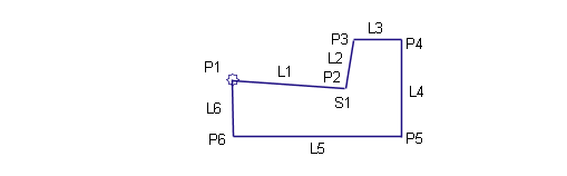
Point, Link, and Shape Codes
The following table lists the point, link, and shape codes for this subassembly that have codes assigned to them. Point, link, or shape codes for this subassembly that do not have codes assigned are not included in this table.
|
Point, Link, or Shape |
Codes |
Description |
|---|---|---|
|
P1 |
Flange |
Flange of channel |
|
P2 |
Invert level_Channel |
Invert level of the channel |
|
P3 |
TopKerb |
Top of kerb |
|
P4 |
BackKerb |
Back of kerb |
|
L1, L2, L3 |
Top, Kerb |
Kerb links on finish surface |
|
L4 |
Datum |
|
|
S1 |
Kerb |
Coding Diagram