In this exercise, you will use the existing offset alignments and profiles of the primary road to create a junction, and then add the new junction to the existing primary road corridor.
The workflow that is demonstrated in this exercise is useful when you need to create several junctions along a single corridor. You define the offset geometry for the primary road, and then reuse it for subsequent junctions.
Specify the junction location and primary road
- Open Intersection-Create-3.dwg, which is located in the tutorials drawings folder.
This drawing contains a junction of two alignments, Road A and Road C. Offset alignments exist on either side of Road A, and there is an existing junction north of Road C.
- Click tab
 panel drop-down Find.
 - In the drawing, click the junction point of the Road A and Road C alignments.
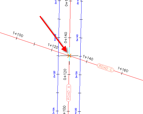
- Click the Road A alignment to specify it as the primary road.
Specify the corridor gradient parameters
- In the Create Junction wizard, on the General page, under Junction Corridor Type, select Primary Road Crown Maintained.
- Click Next.
Specify the horizontal geometry parameters
- On the Geometry Details page, click Offset Parameters.
- In the Offset Parameters dialog box, under Primary RoadLeft Offset Alignment Definition, for Use An Existing Alignment, select Yes.
- For Alignment Name, click
 .
. - In the Junction Offset Alignment Name dialog box, click
 .
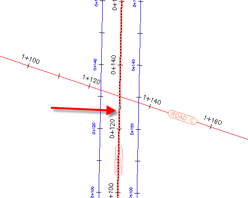
. - In the drawing, select the offset alignment on the left-hand side of the Road A alignment.
- Click OK.
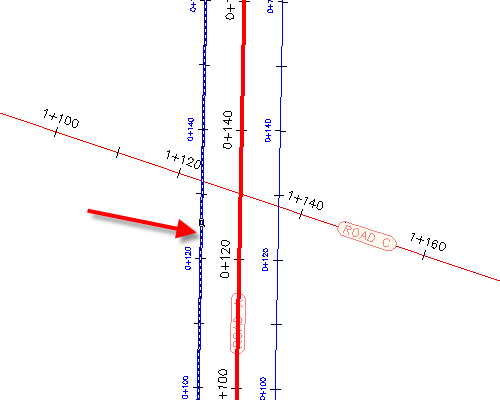
- In the Junction Offset Parameters dialog box, for Right Offset Alignment Definition, repeat Steps 2 through 6 to assign the offset alignment that is on the right-hand side of the Road A alignment.
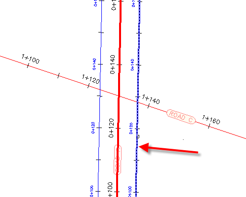
- Click OK.
- On the Geometry Details page, click Radius Kerb Parameters.
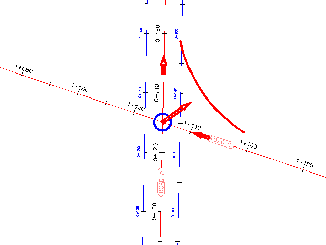
The default parameters for the first junction quadrant are displayed in the Junction Radius Kerb Parameters dialog box. In the drawing, the first quadrant is highlighted, and arrows indicate the direction of incoming and outgoing traffic.
- In the Junction Radius Kerb dialog box, under Junction Quadrant, select SE - Quadrant.
- SE - Quadrant, select the Widen Turning Lane For Incoming Road check box.
- Under Junction Quadrant, select NW - Quadrant.
- NW - Quadrant, select the Widen Turning Lane For Incoming Road check box.
- Click OK.
- In the Create Junction wizard, make sure that the Create Offset And Radius Kerb Profiles check box is selected.
- Click Next.
Specify the vertical geometry parameters
- On the Geometry Details page, under Offset and Corner Radius Profiles, click Lane Crossfall Parameters.
- In the Intersection Lane Crossfall Parameters dialog box, under Primary RoadLeft Offset Alignment Definition, for Use An Existing Alignment, select Yes.
- For Profile Name, click .
- In the Junction Offset Alignment Name dialog box, select Road A - -2.000%.
- Click OK.
- In the Junction Offset Parameters dialog box, for Right Edge Profile Definition, repeat Steps 2 through 5 to assign the offset profile that is on the right-hand side of the Road A alignment. Use profile Road A - -2.000% (1) as the Right Edge Profile DefinitionProfile Name.
- Click OK.
Specify the corridor parameters
- On the Corridor Regions page, specify the following options:
- Create Corridors In The Junction Area: Selected
- Add To An Existing Corridor: Selected, Corridor - (1)
- Select Surface To Daylight: Existing Ground
- Under Select Assembly Set To Import, click Browse.
- In the Select Assembly Set File dialog box, navigate to the Assemblies folder.
- Select _Autodesk (Metric) Assembly Sets.xml. Click Open.
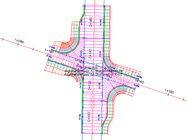
- Click Create Junction.
The junction is created, and new corridor regions are created in the junction area.
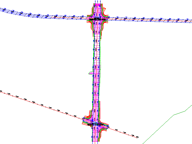
Further exploration: To extend the corridor between the two junctions, add a corridor region between the two junctions.
To continue to the next tutorial, go to Editing Junctions.