In this exercise, you will add a free curve and a free transition-curve-transition to a simple alignment.
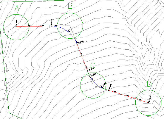
The drawing contains a simple alignment consisting of three straights. In the next few steps, you will add free curves at circles B and C.
This exercise continues from Exercise 1: Creating an Alignment with the Alignment Layout Tools.
Add a free curve between two straights
- Open Align-2.dwg, which is located in the tutorials drawings folder.
- Set your drawing window so that you can see circles B and C on the surface.
- If the Alignment Layout Tools toolbar is not open, select the alignment. Right-click and click .
- In the Alignment Layout Tools toolbar, click the drop-down list
 . Select
  Free Curve Fillet (Between Two Elements, Radius).
- As prompted on the command line, click the straight that enters circle B from the left (the ‘first element’).
- Click the straight that exits from circle B on the right (the ‘next element’).
- Press Enter to select the default value of a curve less than 180 degrees.
- Enter a radius value of 200. The curve is drawn between the straights as specified.
Add a free transition-curve-transition between two straights
- In the Alignment Layout Tools toolbar, click the arrow next to
 . Select Free Transition-Curve-Transition (Between Two Elements).
- As prompted on the command line, click the straight that enters circle C from the left (the ‘first element’).
- Click the straight that exits circle C on the right (the ‘next element’).
- Press Enter to select the default value of a curve less than 180 degrees.
- Enter a radius value of 200.
- Enter a transition in length of 50.
- Enter a transition out length of 50.
Note:
Notice that default values that are shown on the command line.
- Exit the layout command by right-clicking in the drawing area.
To continue this tutorial, go to Exercise 3: Adding Floating Curves to an Alignment.