In this exercise, you will create a corridor assembly with transitions.
Create an assembly baseline
- Open Corridor-2a.dwg, which is available in the tutorials drawings folder.
- Click tab
 panel drop-down Find.
 - In the Create Assembly dialog box, for Name, enter Transition. Click OK.
- When the ‘Specify assembly baseline location’ prompt is displayed on the command line, click a point in the drawing to place the assembly.
The viewport zooms to the assembly baseline, which looks like this:
Add a lane subassembly
- If the Tool Palette containing the subassemblies is not visible, click Home tab Palettes panel Tool Palettes Find.
- In the tool palette, right-click the Tool Palettes control bar. Click Civil Imperial Subassemblies.
- Click the Basic tab.
- Click
 BasicLaneTransition.
 - In the Properties palette, under ADVANCED, specify the following parameters:
- Side: Right
- Default Width: 14.0000
- Depth: 1.0000
- Transition: Change Offset And Level
- In the drawing, click the marker point on the assembly baseline.
A lane is drawn, extending 14 feet to the right, with a gradient of -2% and a depth of 1 foot.
Add a kerb and channel subassembly
- In the tool palette, click
 BasicKerbAndChannel.
 - In the Properties palette, under ADVANCED, specify the following parameters:
- Side: Right
- Channel Width: 1.2500
- In the drawing, click the marker point at the top-right edge of the lane to draw the kerb and channel.
Add a sidewalk subassembly
- In the tool palette, click
 BasicSidewalk.
 - In the Properties palette, under ADVANCED, specify the following parameters:
- Side: Right
- Buffer Width 1: 2.0000
- Buffer Width 2: 3.0000
- In the drawing, click the marker point at the top back-side of the kerb to add the sidewalk and its buffer zones.
Add a ditch subassembly
- In the tool palette, click
 BasicSideSlopeCutDitch.
 - In the Properties palette, under ADVANCED, specify the following parameters:
- Side: Right
- Cut Gradient: 3.000:1
- In the drawing, click the marker point at the outside edge of the outer sidewalk buffer zone to add the cut-and-fill gradient.
Add a transition lane subassembly
- In the tool palette, click BasicLaneTransition.
- In the Properties palette, under ADVANCED, specify the following parameters:
- Side: Left
- Default Width: 12.0000
- Depth: 1.0000
- Transition: Hold Gradient, Change Offset
- In the drawing, click the marker point on the assembly baseline. A lane is drawn, extending 12 feet to the left, with a gradient of -2% and a depth of 1 foot.
Mirror the subassemblies outside the right lane
- Press Esc to exit subassembly placement mode.
- In the drawing, on the right-hand side of the assembly, select the kerb, sidewalk, and daylight subassemblies. Right click. Click Mirror.
- Click the marker point at the top-left edge of the transition lane to draw a mirror of the kerb, sidewalk, and daylight subassemblies.
The subassemblies are displayed on the left side of the assembly marker.
The Mirror command creates a mirror image of the selected subassemblies. All the subassembly parameters, except for the Side parameter, are retained.
Note:The parameters of the mirrored subassemblies are not dynamically linked. If you change a parameter value for a subassembly on one side of the assembly baseline, the change will not be applied to the opposite side.
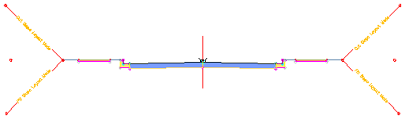
The finished assembly looks like this:
To continue this tutorial, go to Exercise 2: Creating a Corridor with a Transition Lane.