In this exercise, you will learn how feature lines interact when they cross each other at and between vertices.
This exercise continues from Exercise 2: Adjusting Grading Triangulation with a Feature Line.
To work with crossing feature lines
- In the right viewport, select feature line ABC. Right-click. Click Level Editor.
The Grading Level Editor displays a list of the intersection points (
 PIs, or horizontal geometry points) and level change points (
 vertical geometry points) along the feature line.
Notice that the
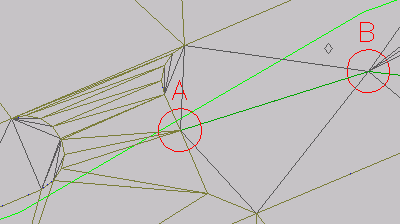
 icon is displayed in the first row. This icon indicates that the building pad feature line also has a PI at this point. When two feature lines cross at a common vertex, both vertices must share the same level value. The level for both feature lines at this point is determined by whichever feature line was most recently edited. In the following illustration, the common vertex is in Circle A.
- In the Grading Elevation Editor click
 Unselect All Rows. Click
  Flatten Gradient Or Levels.
- In the Flatten dialog box, select Constant Gradient. Click OK.
Notice that in the Grading Level Editor, the Gradient Ahead and Gradient Back values are updated to a consistent value. When you flatten a feature line, the points between the start level and the end level are set to the same gradient, effectively eliminating the gradient breaks. You may flatten either the entire feature line, or a selection of points.
- In the
 row, in the Level column, change the level value to 402.00’.
- In the Grading Level Editor, click
 Select A Feature Line, Plot Line, Or Survey Figure.
- In the drawing window, click the building pad feature line.
The level points of the building pad are now displayed in the Grading Level Editor.
- Locate the row containing the icon.
Notice that the value in the Level column is 402.000’, which is the same value you entered for the other feature line in step 4. Change the Level value to 405.000’.
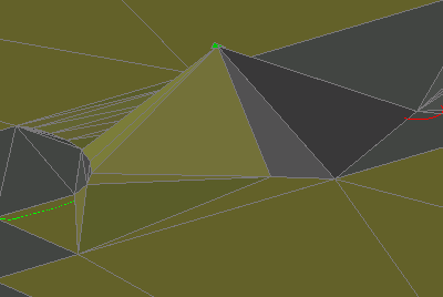
In the left viewport, notice that the value you entered for the shared vertex updated the level of both feature lines. As you see in the following image, the new common feature line level affected the infill gradings of both the ramp and gray infill area. When two feature lines share a vertex, the level of both feature lines at that vertex is determined by whichever of the feature lines was most recently edited.
- In the Grading Level Editor, in the row, change the Level value to 400.00’.
- In the right viewport, select feature line ABC. Using the grip inside Circle A, move the beginning point of the feature line toward the lower left of Circle A.
Note:
You may need to hover over the feature line, and then use Shift+spacebar to select the feature line.
- Right-click the feature line. Select Level Editor.
In the Grading Level Editor, the
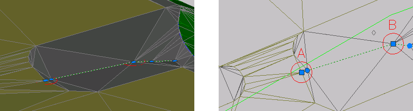
 icon indicates the point at which the feature line crosses the building pad. The white triangle indicates a split point, which is created when two feature lines cross at a location where neither one has a PI. Much like a shared vertex point, a split point acquires the level of the feature line that was most recently edited. If the other feature line has a different level, it gets a gradient break at the crossing point.
Unlike a shared vertex, there is not an actual point at a split point, so you cannot directly edit the level. When you edit one of the feature lines, its gradient runs straight through the intersection, forcing the other feature line to break at the split point. You can use the Insert PI command to create a permanent point at that location on one of the feature lines. After you convert a split point to a permanent point, you can edit the level of a split point directly, and have better control over that point.
- Select the grip at the beginning point of the feature line. On the command line, enter END to apply an endpoint OSNAP. Snap the feature line to the building pad feature line.
Notice that an
 level change point with an level of 402.000’ was added in the second row. The change point was added because you changed the level of the endpoint (the shared vertex) of this feature line to 402.000’ in step 4. When you changed the level of the shared vertex on the building pad feature line to 400.000’ in step 8, the gradient break point was created. The gradient break point ensures that the level of this feature line would match the level of the building pad.
- In the Grading Level Editor, click . Click Flatten Gradient Or Levels.
- In the Flatten dialog box, select Constant Gradient. Click OK.
The gradient flattens, and the levels updates to accommodate the new gradient.
This exercise uses Grading-7.dwg with the modifications you made in the previous exercise, or you can open Grading-8.dwg from the tutorials drawings folder.