In this exercise, you will create the layout profile. Typically, this profile is used to show the levels along a proposed road surface or a finished gradient.
The layout profile is similar to a horizontal alignment, in that it is constructed of straight straights with optional curves placed where the straights intersect. These straights and curves on a layout profile are located in the vertical plane and the intersection points are called vertical intersection points (VIP).
This exercise continues from the Using Surface Profiles tutorial.
Hide the offset profiles
- Open Profile-2C.dwg, which is located in the tutorials drawings folder.
- Click the bottom grid to select profile view PV-1. Right-click. Click .
- In the Profile View Properties dialog box, on the Profiles tab, clear the Draw check boxes for the right offset and left offset profiles.
The Profiles tab displays all existing profiles for a given horizontal alignment, both surface profiles and layout profiles. You can use the Draw check boxes to specify which profiles to display in the profile view.
Further exploration: You can permanently delete a profile by selecting it in the drawing (or in Toolspace) and pressing the Delete key. If you delete a profile, it is removed from all profile views, the list of profiles in the Profile View Properties dialog box, and Toolspace. To restore a deleted surface profile, create a new one. The new profile is displayed in any applicable profile views, and can be edited in the Profile View Properties dialog box.
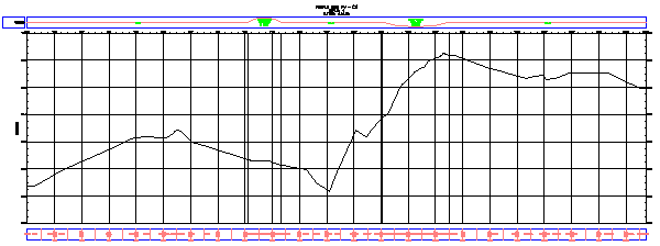
To continue with this exercise, ensure that the centerline profile is visible in profile view PV- (1).
- Click OK.
Specify the profile creation settings
-
Note:
Turn off Object Snap (OSNAP).
- Click tab
 panel drop-down Find.
 - Click the bottom grid to select profile view PV-1.
- In the Create Profile – Draw New dialog box, change the Profile Style to Finished Ground.
- In the Profile Label Set list, select Standard. Click
 .
. - In the Profile Label Set dialog box, on the Labels tab, specify the following parameters:
- Type: Horizontal Geometry Points
- Profile Horizontal Geometry Point: Chainage & Type
- Click Add.
- In the Geometry Points dialog box, examine the geometry points that can be labeled. You can specify any combination of points that you want to label. Click OK. Note:
For more details about geometry point labels, see the Adding Labels in Groups tutorial exercise.
- In the Profile Label Set dialog box, click OK.
- Click the Design Criteria tab.
The options on this tab are used only if you want to ensure that the profile design meets specified design criteria. You will not apply design criteria to the profile in this exercise. You will learn how to use the design criteria feature in the Designing a Profile that Refers to Local Standards tutorial.
- Click OK to accept the settings.
Draw the layout profile
- In the Profile Layout Tools toolbar, click the arrow on the right side of
 and click Curve Settings.
 - On the Vertical Curve Settings dialog box, specify the following parameters:
- Curve Type: Parabolic
- Crest Curve Length: 100
- Sag Curve Length: 100
Notice that you can select one of three curve types and specify parameters for each type.
- Click OK.
- In the Profile Layout Tools toolbar, ensure that Draw Straights With Curves is selected.
You are now ready to draw the layout profile by clicking in the drawing at the proposed locations of VIPs. At each VIP, the application inserts a curve. To be realistic, your line should follow the general profile of the surface centerline. However, it can cut across steep hills and valleys to outline a smoother road surface.
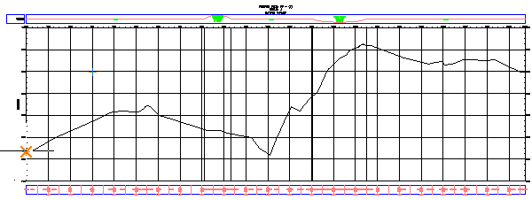
- In the profile view, click the left side, near the centerline surface profile, to start the layout profile.
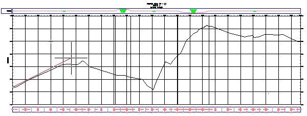
- Extend the line to the right and click at another location near the centerline surface profile. Continue in this manner.
- At the last point, right-click to end the profile. The layout profile is now drawn and labeled.
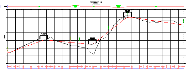
- Zoom and pan along the layout profile to examine the labels.
To continue this tutorial, go to Exercise 2: Editing a Layout Profile.