In this exercise, you will edit the profiles that define the vertical geometry of a junction object. You will edit the profiles graphically and parametrically, and examine how the changes affect the junction.
Examine locked VIPs
- Open Intersection-Edit-Vertical.dwg, which is located in the tutorials drawings folder.
This drawing contains a junction of a primary road (Road A) and a side road (Road C).
- In the lower right viewport, select the layout profile.
Notice that
 lock icons are displayed on three of the VIPs. The lock icons indicate that the VIPs are locked to another profile. When the junction was created, the middle VIP was created at the point where the side road intersects with the primary road profile. The other two VIPs were created to maintain the primary road crown through the junction, and are locked to the edges of the primary road.
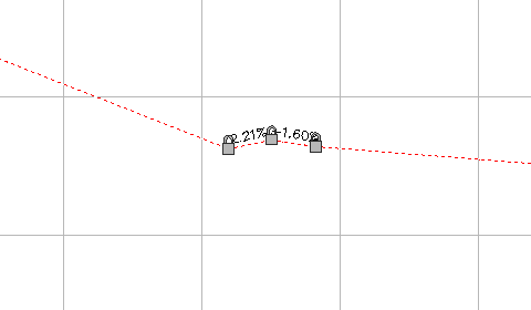
- Click tab
 panel Find.
 - On the Profile Layout Tools toolbar, click
 .
. In the Profile Elements vista, notice that a
 is displayed in the Lock column for VIPs 5 through 7.
 - Hover the cursor over the icon for VIP 6.
Information about the locked VIP, including alignment, profile, and junction, is displayed in a tooltip. VIPs that are created as part of the junction creation process are dynamically linked to the primary road profile.
Note:You can unlock a VIP by clicking the icon. If a VIP is unlocked, the profile will no longer react to changes in either the junction or primary road profile.
- Click the
 icon for VIP 8.
 The VIP is locked at the current chainage and level. Notice that another
icon is displayed on the profile, and the VIP Chainage and VIP Level values are no longer available. A VIP can be manually locked to a specified chainage and level value. Manually locked VIPs are not affected by modifications to other portions of the profile. 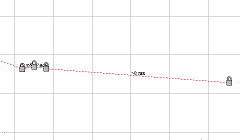
- Close the Profile Layout Tools toolbar.
- In the left viewport, select the junction marker.
On the ribbon, the Junction tab is displayed. Tools for adjusting the side road profile are displayed on the Modify panel. You can edit the primary road profile with the standard profile editing tools.
Modify the side road gradient
- Click tab Modify panel Side Road Profile Find.
The Side Road Profile Rules dialog box is displayed. Use this dialog box to specify the side road gradient entering and exiting the junction.
- In the Side Road Profile Rules dialog box, specify the following parameters: Note:
Enter the parameters in the following order.
- Apply Gradient Rules: Yes
- Distance Rule To Adjust The Gradient:
Specify Distance
This option enables you to specify a distance from the junction of the primary and side road alignments. This enables you to extend the side road gradient rules outside the extents of the junction.
- Distance Value: 100.000m
- Maximum Gradient Change: 2.00%
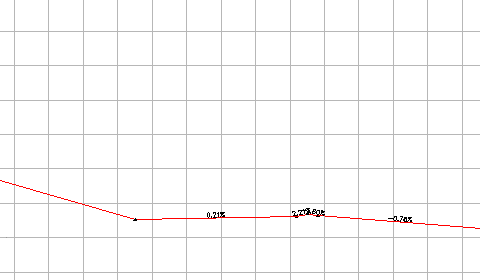
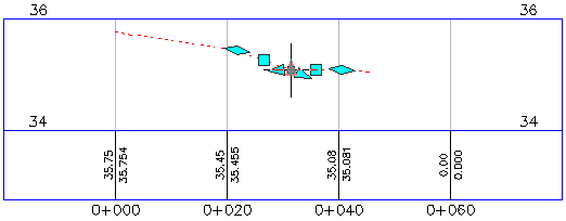
In the lower right viewport, a new VIP is created 100 meters to the left of the locked VIPs. The gradient entering the junction is 0.21%, which is exactly 2.00% less than the primary road gradient.
- In the lower right viewport, select the layout profile.
You can move the grip at the VIP to make minor changes to the profile. If you drag the grip outside the range of parameters specified in the profile gradient rules, the grip snaps back to the default position that satisfies the gradient rules.
- Close the Side Road Profile Rules dialog box.
- Press Esc.
Add a low point to a radius kerb profile
- In the upper right viewport, zoom in to the Junction - 2 - (SE) profile view.
- Select the profile.
The
 grips indicate the extents of the radius kerb profile. The profile portions that are outside the extents represent the offset profiles. Changes to the offset profiles affect the radius kerb profiles, but changes to the radius kerb profile do not affect the offset profiles. Use the grips to extend the radius kerb profile along either offset profile.
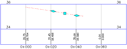
- Click tab panel Find.
- On the Profile Layout Tools toolbar, click
 Insert VIP.
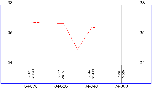
 - Click between the two grips to place a VIP, creating a low point on the radius kerb.
A low point facilitates drainage along a radius kerb. In the following procedures, you will see how the radius kerb reacts to changes in other objects.
- Close the Profile Layout Tools toolbar.
Move the primary road alignment
- In the left viewport, select the Road A alignment.
- Select the grip at the southern end of the Road A alignment. Drag the grip to the left. Click to place the grip.
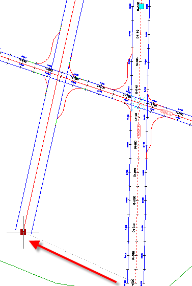
In the bottom right viewport, notice that the three dynamically locked VIPs moved to a new location. This happened because you moved the alignment to which they are locked.
In the top right viewport, examine how the changes to the junction location affect the radius kerb profile that you modified.
Change the primary road profile level
- In the top viewport, pan to the Road A profile view.
- In the Road A Profile view, select the layout profile.
- Select the second
 PI grip from the left. Drag the grip up. Click to place the grip.
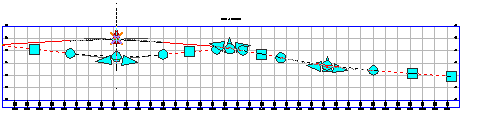
In the bottom viewport, notice that the three locked VIPs moved up to accommodate the new primary road level.
In the top right viewport, the VIP you added to the southeast radius kerb has stayed in the location you specified, but the ends of the profile moved up to accommodate the new level of the offset profiles. The ends of the radius kerb profile are locked to the offset profiles. You must manually update VIPs that have been placed within the profile.
To continue this tutorial, go to Exercise 3: Creating and Editing a Corridor in the Junction Area.