In this exercise, you will examine how the daylight subassemblies are applied to the corridor model in section. You will notice chainages at which the current daylighting parameters are inappropriate for the site conditions.
Examine the existing corridor
- Open Assembly-2a.dwg, which is available in the tutorials drawings folder.
The drawing contains two viewports. A completed corridor assembly is displayed in the top viewport. A surface, corridor, and profile view are displayed in the bottom viewport.
- In the bottom viewport, select the corridor. Click tab
 panel
panel  .
. - On the Section Editor tab, use the


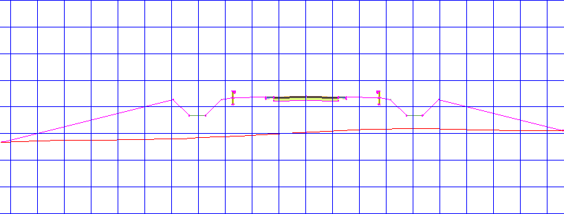
 buttons to examine how the Through Road assembly is applied to at the corridor chainages.
 The assembly creates a ditch on either side of the road. At the beginning and end of the corridor, the cut and fill is relatively consistent on both sides.
In the following exercises, you will address two conditions:
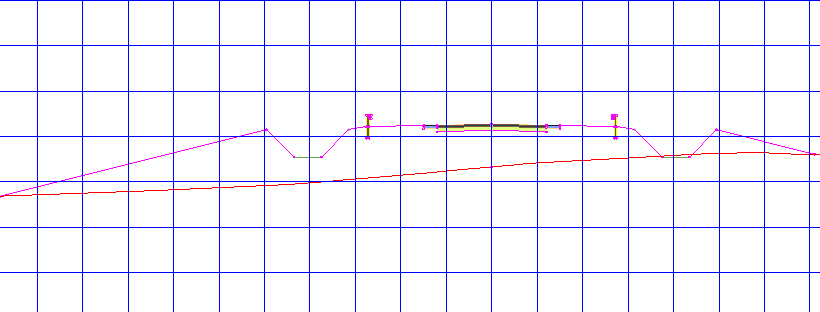
- First, the fill condition from chainages 0+00 through 1+00 produces a relatively deep fill on the left side. While the corridor assembly is constructed appropriately for other regions of the corridor, you will modify the design to use a different approach in this region.
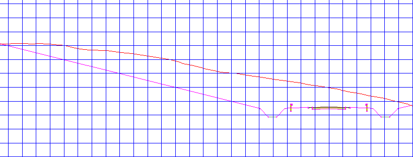
- Second, from chainages 5+00 through 8+00, a much greater amount of material must be cut from the left side of the corridor. While the Through Road assembly is appropriate for most the corridor, it is not ideal for these chainages.
- First, the fill condition from chainages 0+00 through 1+00 produces a relatively deep fill on the left side. While the corridor assembly is constructed appropriately for other regions of the corridor, you will modify the design to use a different approach in this region.
- In the View/Edit Corridor Section Tools toolbar, click to return to chainage 0+00.
To continue this tutorial, go to Exercise 2: Adding Conditional Subassemblies to a Corridor Assembly.