Usage of the Advanced Data Manipulation tools in Particle Flow is potentially quite complex. The more you know about its workings, the more you can do with it. This tutorial aims to give you a leg up by demonstrating how to create an operator that lets you control particle direction with a 3D object such as a teapot.
Skill level: Intermediate
Time to complete: 1 hour
Part 1: Create a Data Operator
To create a new operator, you can use any of the Data operators: Data Icon, Data Operator, Data Test, or Data Icon Test.
- Start or reset 3ds Max, and then create a default Particle Flow system. Press 6 to open Particle View.
- From the Particle View depot, drag and drop the Data Icon operator on top of the Speed operator in Event 001, so that when you release the mouse button, the Data Icon operator replaces the Speed operator.

- Click the Data Icon 001 operator.
The Data Icon 001 rollout appears in Particle View.
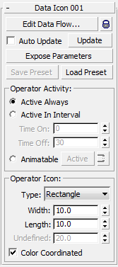
- At the top of the rollout, click the Edit Data Flow button.
This opens Data View, the user interface for Data operators. Data View works very much like Particle View.
For the first part of this exercise, you'll create a simple operator that defines particle speed with three numeric values. The creation and modification of particle properties is done by wiring different suboperators in Data View. In this example you'll use the Scalar suboperator.
- From the Data View depot, drag and drop three Scalar suboperators—one for each vector component—into the main window.
By default, the Dynamic Names feature is on, so each new suboperator assumes its most important setting or settings as a name. In this case, it's the Value setting: 1.0. You'll give the Scalar suboperators more meaningful names.
- Right-click the suboperators in turn and rename them Speed X, Speed Y, and Speed Z.
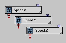
Next you'll define the initial values.
- Click the Speed X suboperator.
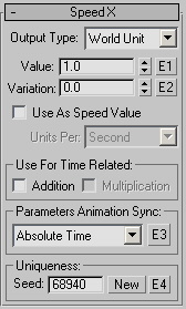
Its parameters appear on the Speed X rollout.
-
Right-click the Value spinner to set it to 0.0, and then turn on Use As Speed Value. Keep the default Units Per setting: Second.

- Do the same with the Speed Y suboperator.
- Set Speed Z
 Value to 200.0 and turn on Use As Speed Value.
 Next, you'll wire the data created by the Scalar suboperators into a speed data channel for the particles.
- Drag an Output Standard suboperator into Data View, below the Scalar suboperators.

The purpose of the Output Standard suboperator is to take data calculated within the Data operator and convert it to information that the Particle Flow system can use. Thus, it has only an input; its output is meaningful only in the context of Particle View. Its default dynamic name is Position Vector because it's set to output position data in vector format.
- Click the Output Standard suboperator, and then, on its rollout, choose Speed, and from the drop-down list, choose Vector.
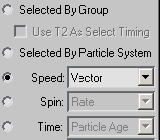
The suboperator's dynamic name is now Speed Vector.
- In the Data View window, drag from the output connector of the Speed X suboperator to the input connector of the Output Standard suboperator.
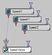
When you release the mouse button, a Convert suboperator automatically appears between the two suboperators you're linking. This is standard behavior in Data View when you attempt to wire together two connectors of different but compatible data types.
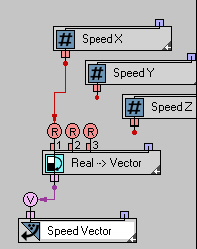
Thanks to dynamic naming and the color coding of the inputs and output, you can see that the new suboperator is automatically set to convert real (scalar) data to a vector value.
- Wire the output of the Speed Y suboperator to the second input (R2) of the Convert suboperator. Likewise, wire Speed Z to R3 of the Convert suboperator.
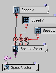
That's it! You've created a simple operator.
- Scrub the time slider or play the animation. If necessary, move the dialogs to get a clear view of the viewport.
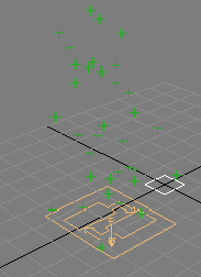
The particles move upward, in the positive Z direction, as instructed by your custom operator.
Tip: If the particles don't move as expected, then in Particle View, on the Data Icon 001 rollout, click Update. Then play the animation again.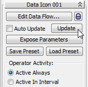
In the steps and procedures that follow, you might need to use Update, too.
- In Data View, highlight the Speed Z suboperator, try different Value settings, then scrub the time slider.
The particles reflect the speed change.
- Highlight the Speed Y suboperator, give it a positive Value, then scrub the time slider.
The particles move horizontally to reflect a change in speed along the Y axis.
Use the Icon to Control Particle Motion
Next, you'll make your operator more complex by linking the speed vector to the orientation of the operator icon. This is the small square at the world origin that was created when you added the Data Icon operator.
- In Particle View highlight the Data Icon operator, if necessary, and then in the Data Icon 001 rollout
 Operator Icon group, change the Type from Rectangle to Arrow.
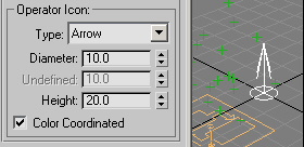
The icon changes to an arrow, which makes it easy to see its orientation.
You can use the Icon suboperator to request the transformation matrix of the icon.
- In Data View, drag the Icon suboperator from the depot to an empty area of the schematic window.
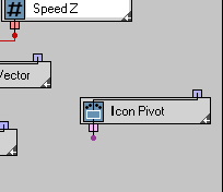
-
Click the Icon Pivot suboperator and then, from the Icon Property drop-down list, choose Icon TM. TM stands for transformation matrix.
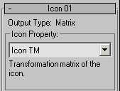
You'll use the Function suboperator to multiply the speed vector by the icon matrix.
- Add a Function suboperator in an empty part of the window.
- Click the Function suboperator and then set the Second Operand
 Type to Matrix. Also set Function to Vector Transform.
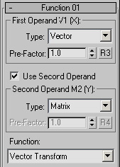
-
Click the wire between the Convert suboperator (Real --> Vector) and the Output Standard suboperator (Speed Vector) to highlight it and then press Delete to remove it.
- Wire the output of the Convert suboperator to the V1 input of the Function suboperator.
-
Wire the output of the Icon suboperator to the M2 input of the Function suboperator. Note that you're wiring between the same-color connectors.
- Wire the output of the Function suboperator to the input of the Output Standard suboperator.
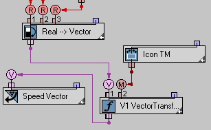
Now the icon orientation controls the direction of the particles.
- Rotate the icon about the X and Y axes.
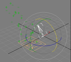
As you rotate the icon, the direction of the particle stream changes accordingly.
Replace the Icon with a Reference Object
It's just as easy to use a reference object's orientation to set the particle direction.
- Add a teapot to the scene.
- In the Data Flow window, click to highlight the Icon TM suboperator and then press Delete to get rid of it.
- Add a Select Object suboperator to an empty area of the Data Flow.

- Click to highlight the Select Object suboperator, then on the Select Object 001 rollout, click the Single Object button (which initially reads "None"). In a viewport, click the teapot.
The teapot's name appears on the button and on the suboperator node.
- Next, add an Object suboperator.
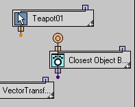
This lets you specify which object property to retrieve.
- Highlight the Object suboperator and then, from the Object Property drop-down list, choose Object TM.
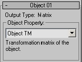
- Connect the Select Object suboperator to the Object suboperator, and then connect the Object suboperator to the M2 input of the Function suboperator.
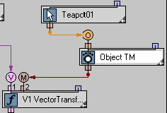
Now, when you rotate the teapot about the X and Y axes, it has the same effect on the particle stream as did rotating the icon.

Part 2: Save the Data Operator as a Standard Operator
Once you've created a Data operator, you can save it as a regular Particle Flow operator. First, you expose the most important parameters. In this case, they're the vector components; that is, the Scalar suboperator Value settings, and the button of the Select Object suboperator.
- In Particle View, make sure the Data Icon operator is highlighted. On the rollout, click the Expose Parameters button.
This opens the Expose Parameters dialog, which lets you collect and identify the parameters to be exposed. Basically, you use it to create your operator UI.
- In the left-hand list, highlight the Value entry under Speed X. In the Label Field below the list, type X:, and then click the Add button.
The entry in the left-hand list changes to [Value -> X:)], and the new label appears in the right-hand list.
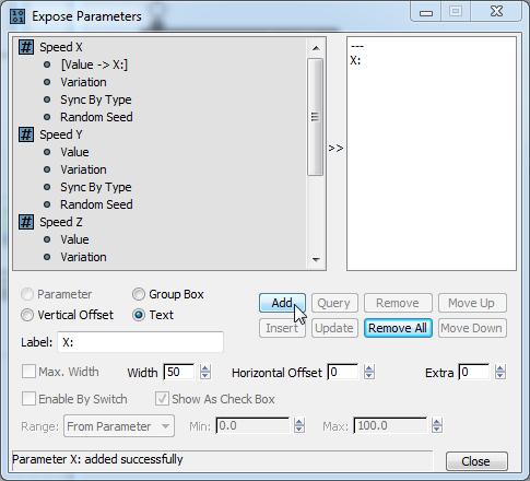
More important, the added parameter appears on a new Parameters rollout in Particle View. This shows the exposed parameters, and is available to anyone who uses your operator.

-
Do the same for Speed Y
 Value and Speed Z
  Value, labeling them Y: and Z:, respectively.
 - Also add Teapot001
 Object, labeling it Reference Object:. Set Width to its maximum of 95 so there's enough room for the button and label on the rollout. Then choose Group Box. Finally, click Add.
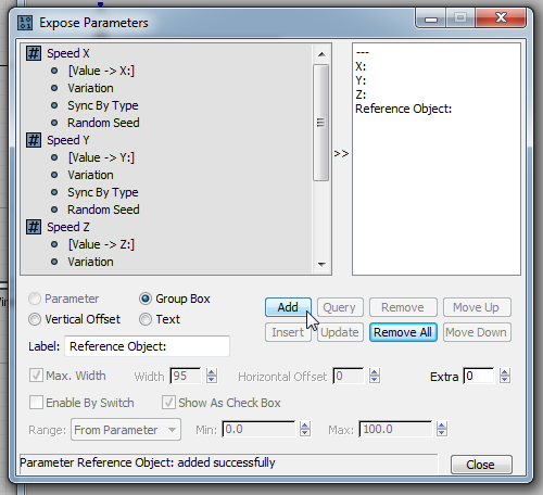
- On the Expose Parameters dialog, click the Close button.
All four parameters now appear on the Parameters rollout.
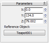
The next step is to save the Data operator as a preset.
- On the Control rollout in Particle View, click the Save Preset button.
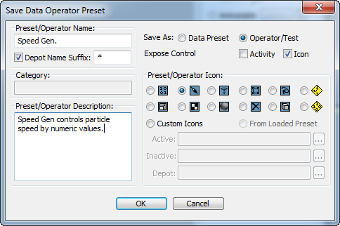
This opens the Save Data Operator Preset dialog.
-
In the Preset/Operator Name field, enter a name, such as Speed Gen.
-
To the right of this field, set Save As to Operator/Test.
-
In the Preset/Operator Description field, enter a description, such as this one: Speed Gen controls particle speed by numeric values..
- In the Preset/Operator Icon group, choose any icon you like.
- Click the OK button.
A message informs you that the preset has been saved.
- In order to get the operator to show up in the Particle View depot, you need to quit 3ds Max and then restart. Do so now.
- Add a PF Source object and a teapot. Press the 6 key to enter Particle View.
Now the Depot contains your new operator. The name of the operator in the Depot is followed by an asterisk (*), the default suffix, which denotes it as a custom operator.
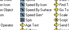
- Drag the Speed Gen operator on top of the default Speed operator in Event 001.
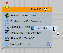
- Click the Speed Gen 001 operator, and then on the rollout in Particle View, click the Reference Object button and then in a viewport, click the teapot.
- Rotate the teapot, then drag the time slider.
The teapot orientation controls the particle stream direction.

Summary
The Advanced Data Manipulation tool set for Particle Flow lets you create your own custom Particle Flow tools.