When you begin learning to simulate particle physics with Particle Flow, the included preset mParticles Flow makes a good starting point. In this tutorial, you use the mParticles Flow in conjunction with other techniques for learning how to use the mParticles system.
Skill level: Intermediate
Time to complete: 1 hour
Preparation for This Tutorial
- If you have not already downloaded the tutorial files (MAX scenes and other assets), download them now and unzip them into a project folder called \Autodesk 3ds Max 2018 tutorials. See Where to Find Tutorial Files.
- On the Quick Access toolbar, click
 (Project Folder) and set your current project to Autodesk 3ds Max 2018 Tutorials.
In the initial sections of this tutorial, you start from scratch, but the final section uses a prepared .max scene file.
Part 1: Explore the Preset mParticles Flow
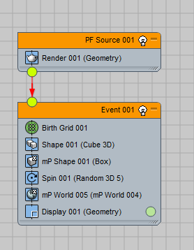
- Start or reset 3ds Max, press 6 to open Particle View, and then drag the mParticles Flow from the depot to the event display.
This adds in one fell swoop all the necessary elements for a simple physics simulation.
- Play the animation.
It starts out with a cubic arrangement of box-shaped particles suspended in mid-air. The particles quickly fall to the ground and end up randomly scattered around the point of impact.
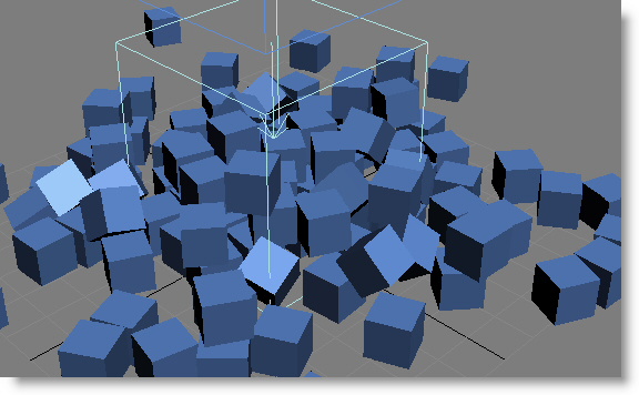
The boxy particles don't do much after they fall, but you can add some rolling action by making them round.
- Click the Shape operator and set Shape to Sphere 20-Sides and Size to 5.0 (the default size of 10.0 would make the particles collide at the start of the simulation, thus flying away instantly). Also click the mParticles Shape operator and set Collide As to Sphere. And last, because the rolling away takes some time, set the animation length to 200 frames.
mParticles Shape determines the particles' characteristics during the simulation.
- Rewind the animation and play it again.
This time the particles fall and then disperse by rolling away.
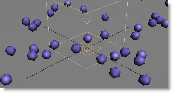
The physics-simulation engine is the mParticles World helper, which you can access from Particle View.
- In Event 001, click the mParticles World operator, and then on its parameters rollout, click the => button.
This selects the helper and shows its Parameters rollout on the Modify panel.
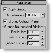 Note: Apply Gravity and Ground Collision Plane are on, but this is not the case when you create an mParticles World helper explicitly, either via the Create panel or from the mParticles World operator; both options are off by default.
 - Try reducing the Acceleration (gravitational, that is) value to 10.0. Increase the animation length to 500 frames.
This time, when you play the animation, the spheres fall much more slowly and take longer to roll away.
Part 2: Create Your Own Simulation
In this section you'll create a simple brick wall and use virtual glue to mortar the bricks.
- Reset 3ds Max and start again with a new mParticles Flow. Set the animation length to 300 frames.
- From the depot, drag a Birth Group operator on top of the Birth Grid operator.
Birth Group replaces Birth Grid and the particles disappear from the viewports. However, the large wireframe cube remains. This is the mParticles World helper. The down arrow pointing to its center indicates the direction of gravity, and the X on the bottom side indicates the location of the ground collision plane. By default, this coincides with the home grid in 3ds Max (the XY plane at Z=0).
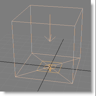 Tip: You might have to move the time slider to update the viewports. Return to frame 0 when you are done.
There is no physical sign of Birth Group in the scene; it creates particles from mesh objects that you specify, as you'll see shortly.
- Delete the Spin operator from Event 001.
The operator isn't necessary for this tutorial.
- Go to the Create panel and add a Box primitive of Length=20, Width=10, and Height=5.
- Activate the Move tool and then right-click the spinners of the Coordinate Display—the X, Y, and Z fields at the bottom of the program window—so the box is centered on the home grid.
- Clone the box by Shift+dragging it along its local Y axis, and release the mouse button when the clone is right next to the original. Use the Clone Options dialog to create five copies, making six bricks in all. Select all six bricks and then position them so the row is lined up along the world Y axis and centered on the X axis.
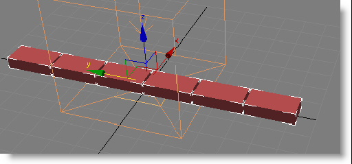
- In the Left viewport, Shift+move the bricks straight up on the view Y axis so the clones are just above the original row, and again make five copies.
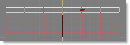
- Click the Birth Group operator and, under the Particle Objects list, which is empty currently, click the By List button next to Add. The Select Objects dialog opens with the text cursor in the Find field. Press the B key to highlight all the Box objects and then click Select.
The Box object names now populate the list, and their particle counterparts appear in the viewports. The boxes are the particle objects; once you've applied them to the operator, you can get them out of the way easily.
- Click the Hide button under the list.
This hides the objects in the list, leaving only their particle counterparts.
- Delete the Shape 001 (Cube 3D) operator.
Now the mParticles Shape 001 (Box) operator governs the shape of the particles, so they are the same size as the original bricks.
- The particle bricks use the Display color; change it if you like.
- Play the animation.
The bricks succumb quickly to the pull of gravity and fall down in stacks.
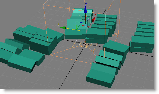
You can fix this easily with the mParticles Glue test.
- Add an mParticles Glue test to the end of Event 001. Click the test so its parameters appear in Particle View. Set Type to Rigid.
The Glue test creates bindings between pairs of particles, so it's important to be able to see what it's doing. Thus a crucial option is Visualize Binding.
- On the Parameters rollout, turn on Visualize Binding.
You can't see the bindings because there aren't any yet.
- Make sure you can see the bricks clearly in the Left viewport, and then use the Bind Distance spinner to increase the value until you see blue lines between the particles in the Left viewport.
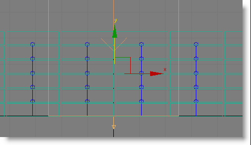
The bindings are mainly vertical because that's the shortest distance between particles.
- As soon as you start to see the bindings, play the animation.
You'll probably see that the columns of bricks move together. We have virtual mortar above and below the bricks, but not on the sides.
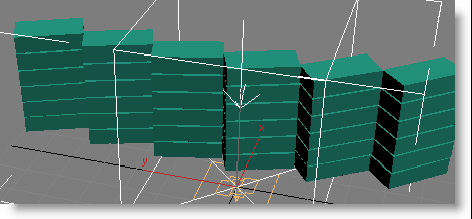
First you need to deal with the columns moving when they shouldn't. This is due to a lack of stability in the simulation, which you can resolve by increasing the Subframe Factor value.
- Click the mParticles World operator, and then on its parameters rollout, click the => button to open the mParticles World helper's parameters on the Modify panel. At the bottom of the panel, expand the Advanced Parameters rollout and set the Subframe Factor value to 10.
The general rule of thumb for setting the Subframe Factor value is to double the Glue test
 Max Binds p/Particle value and add 2. So, if Max Binds p/Particle is 4, then Subframe Factor should be set to (2 x 4) + 2=10. Sometimes you can get away with a lower Subframe Factor value, depending on the general complexity of your simulation. But for now, use 10.
 If you set this value while the columns are disarrayed, you'll see them jump back to their original positions.
Important: Increasing the Subframe Factor value improves the accuracy of the simulation by applying the settings more times per frame; this can slow down the simulation, but in many cases is transparent. When working with your own simulations, if you see any instability, try increasing the Subframe Factor value; chances are this will improve stability. - Play the animation again and make sure things are more stable; if not, increase the Subframe Factor value further.
Next, to allow the columns to bind together, you'll increase the possible number of bindings.
- Click to highlight the Glue test, and set Max Binds p/Particle to 8. Increase Bind Distance until you start to see diagonal lines: The Bind Distance value will probably be between 20 and 30.
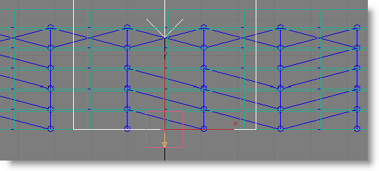
You probably won't see bindings between every pair of horizontally adjacent bricks, but as long as you have at least one or two horizontal bindings for each column, the whole wall should hold together.
- Play the animation.
Ideally, nothing should happen. If the wall moves, increase the Subframe Factor value until it doesn't.
Part 3: Hit the Wall with a Ball
To create particle interaction, you'll add a Birth Stream emitter.
- From the depot, drag a Birth Stream operator next to Event 001 so it creates a new event. Set the Display operator to Geometry, and then add a Shape operator and a mParticles Shape operator after Birth Stream, both set to Sphere. Wire the event to the PF Source global event. Important: Makes sure the Shape operator precedes the mParticles Shape operator in the event. Because event elements are handled in order from top to bottom, the Shape data must be available for mParticles Shape to process; otherwise it won't work correctly.
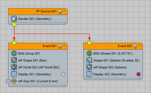
You also need to clone the mParticles World operator so both events use the same mParticles World helper and world setup. You'll do this in a little while.
- Click the Birth Stream operator and set Emit Stop to 0, so that all particles are emitted at once at the start of the animation.
The read-only Total field should now contain 1.
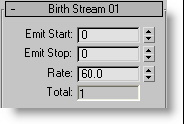
If you play the animation now, you see the single particle come shooting out from under the wall. That's because the default position of the Birth Stream icon is at the world center: (0,0,0). Also, because Birth Stream has a Speed property built in, set to 300 by default, no additional Speed operator is necessary.
- Select the Birth Stream icon and move it about 80 units in the negative X direction, and then move it upward so it's vertically centered on the wall height. The position should be about (–80,0,15).
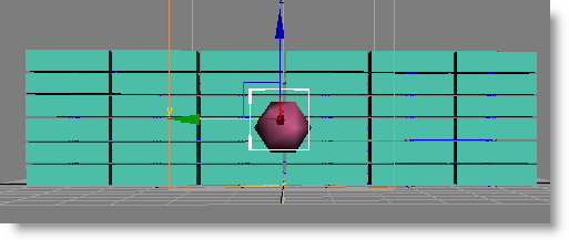
- Rotate the Birth Stream icon –90 degrees along the Y axis, so the vector arrow points at the wall.
- Click the Shape operator and set the Size to 20 to increase the size of the sphere.
- Play the animation.
The sphere goes through the wall without colliding with the bricks. That's because its event isn't participating in the physics simulation yet.
An mParticles World operator needs to be in every event whose particles participate in the simulation. It should always be the last operator in the event except for Display and any tests.
- In Event 001, right-click the mP World 01 event and choose Copy. Then right-click Event 002 and choose Paste.
3ds Max adds an mParticles World event to the sphere event.
- If the new mParticles World event is not at the bottom of Event 002, just above the Display operator, drag and drop it to correct the position. Note: You don't need to use Paste Instanced because there is never more than a single mParticles World operator in a scene: Events that use this operator are part of the same simulation, and changing the mParticles World parameters from one event updates the same parameter settings for all events that include mParticles World.
- Play the animation again.
This time the sphere knocks the wall down. Depending on your setup, it might also then push the wall along as it rolls. The particles remain bound together tightly even when struck by the ball.
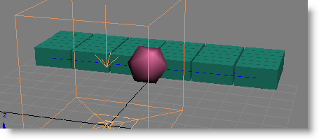
If the ball doesn't knock over the wall at first, try selecting mParticles World and reducing the Apply Gravity
 Acceleration value; for example, to 245. You can also save your work and take a look at the included file
pflow_mparticles_tutorial.max.
Check its settings to see what's different from your setup.
Part 4: Break Things Up
An important parameter group in mParticles Glue is Breakability. You can use its settings to delete the bindings when the particles encounter sufficient force.
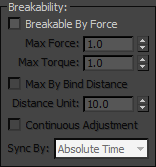
- Click the mParticles Glue test and in the Parameters rollout
 Breakability group, turn on Breakable By Force. Click the > button on the time slider a couple of times while watching a viewport in which the bindings are visible.
 By frame 2, all the bindings are gone. Because the default Max Force and Max Torque settings are low, the gravity force alone is enough to dissolve the bonds.
Max Force and Max Torque define the maximum forces that a binding can withstand before breaking. To create a realistic simulation, you usually need to increase both values.
- At a frame before the ball hits the wall—say, frame 6—increase Max Force and Max Torque until the bindings are visible again. For example, try setting both to 500.
- Continue experimenting with the Max Force and Max Torque settings while playing the animation to see the different effects possible. Also try adjusting the Birth Stream
 Speed value to see how it affects the simulation.
 - When you're done, restore both Max Force and Max Torque to 1.0, and Birth Stream
 Speed to 300.
 - Turn off Breakable By Force.
Part 5: Bricks to Planks
Another useful mParticles Glue option is Bind Center Aligned Only. This creates bindings that are based on particle alignment as well as proximity. With the current arrangement of particle bricks, this would be difficult to see because each brick is aligned with its neighbors, so you'll rearrange the layers slightly.
- Click to highlight the Event 001
 Birth Group operator and then click Unhide to reveal all the mesh shapes used to generate the particles. Then turn off the Birth Group operator so you can see the boxes more easily.
 - Starting with the bottom row, select each alternating row of boxes, then move them about 10 units to the right so each brick is offset from its vertical neighbor by half its length.
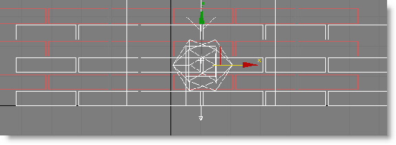
This, of course, is how real-world brick walls are constructed. Also, in the real world, half-bricks are used to fill in the gaps, but that won't be necessary for this tutorial. In fact, in this section you'll make the bricks act like planks, further demonstrating that in the virtual world, anything is possible.
-
Turn the Birth Group operator back on.
The particles are still in their original positions. If you change the particle objects (the boxes), you need to update the Birth Group manually.
- Under the Particle Objects list, click Update Particle From Objects, then hide the particle objects again.
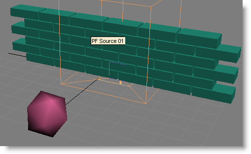
- Click the mParticles Glue test, and with Visualize Binding on, set Bind Distance to 30.
You can see more connections now, mainly because of the offset alternate layers. There were as many before, but now they go diagonally to get to the nearest brick, whose horizontal position is offset.
- Turn on Bind Center Aligned Only.
This eliminates all the diagonal bindings by allowing mParticles Glue to bind only to particles whose local axes are aligned with each other. So bindings can go only at right angles (the way the axes line up), not diagonally.
If you look closely, you can see the horizontal bindings between neighboring particles and the vertical bindings between particles in alternating layers. To create the plank effect, you use a third setting to eliminate the latter.
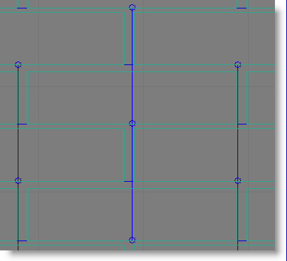
- Turn on Bind Gap.
Bind Gap eliminates bindings beyond the specified distance, so the long-distance bindings between alternating vertical layers, which are much longer than the specified Bind Gap value of 1.0, are no longer enabled. You're left with horizontal bindings only, which provide the desired plank effect.
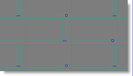
After you turn on Bind Gap, if you don't see the small horizontal bindings between boxes, increase the Bind Gap value until the bindings reappear.
- Play the animation.
The ball breaks up the bricks in such a way that it's apparent that they're acting as planks.
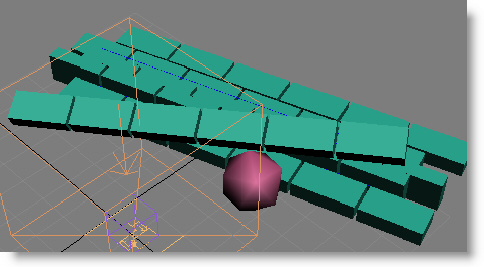
Before moving on to the final procedure, take a quick look at one more Glue setting that enables flexible bindings.
- Rewind the animation, and set the mParticles Glue
 Type parameter to Distance.
 The Distance binding type allows more elasticity in the bindings.
- Play the animation again.
The planks still hold together, but bend upon impact from the ball, as if they're connected by strings rather than being bolted together. The Distance option can produce interesting simulations such as cloth and beaded curtains; you'll find some examples of these in the included sample files.
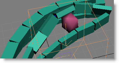
- Set the binding type back to Rigid.
Part 6: Skinning Particles to Break a Box
Particle Skinner is a powerful modifier that lets particles function as "bones" inside a mesh "skin." As you'll see in this brief introduction, this allows for some quick and easy but exciting possibilities for special effects.
For this lesson, you'll go back to the particles that break up as columns.
- Open the included sample scene file, pflow_mparticles_tutorial.max.
- Open Particle View. Move it so you can see the Left viewport, and change the Left viewport to a Wireframe view.
- Highlight the Event 001
 mParticles Glue operator, turn on Visualize Binding, then set Bind Distance to a low enough value that only vertical bindings appear. A value of 10.0 should work.
 - Play the animation and make sure the particles break up into columns.
The problem is that, as there's only one ball, only the center columns are affected by its impact. One way to resolve this is to have more particles.
- Click the Birth Stream operator, and in the Stream Source Icon group, increase the Width value so that the icon is the same width as the wall; about 125 units. Also in Birth Stream set Emit Stop to 1.
Now the Total value is 3, but if you play the animation, the balls are too close together, and still don't affect all the columns. You can adjust their placement with the Uniqueness Seed value.
- Set Seed to 21150 and play the animation.
Not all of the columns are hit, but enough are that they all end up in different positions.
- Go back to frame 0.
- Create a Box primitive that fits snugly around the brick wall. Set Length Segs and Height Segs both to 20, and Width Segs to 5.
In the included sample scene, pflow_mparticles_tutorial.max, the size is 127 x 12 x 34, but this might vary in your scene.
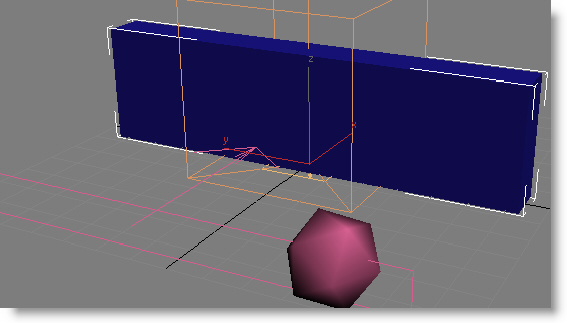
- Apply the Particle Skinner modifier to the box.
- On the modifier Parameters rollout, under Particle Flow Systems, click By List.
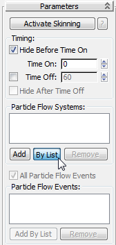
On the Select Particle System dialog, click to select PF Source 01, and then click OK.
The Particle Flow Systems list now contains a single entry: PF Source001. However, not all the particles in this system should affect the box "skin"; just the ones in Event 001.
- In the Particle Flow Systems group, turn off All Particle Flow Events. Then click Add By List and select Event 01.
Particle Skinner works by letting particle motion exert an influence on nearby mesh points. Ideally, all mesh points in the modified object should be influenced by particles; otherwise, they get left behind when the particles move, causing unsightly stretching of the mesh. Thus, a useful option is the ability to check for uninfluenced mesh points, which helps you to set the influence distance to the right amount.
- Expand the Particle Skinner modifier stack entry so you can see the Control Particles sub-object level, and then click Control Particles to highlight it.
- Turn on Activate Skinning at the top of the Parameters rollout, and then scroll down to the Display Parameters rollout, expand it, and turn on Display Unassigned Points.
- Back on the Parameters rollout, in the Distance Influence group, note that the Absolute option is active. Use the spinner to lower the Absolute value until you see small red squares on the box, as depicted in the following illustration (these indicate mesh points that aren't influenced by any particles), and then increase it until you don't see any more from any angle. A value of 7 should be about right.
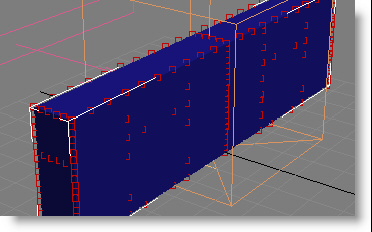 Tip: You can see the number of unassigned points on the Activate Skinning Info dialog, which you open by clicking the ? button next to the Activate Skinning button.
 - Also, in the Rip Surface Apart group, just below the Distance Influence group, set Type to Distance Change.
Now that the basic setup is finished, you don't need to see the "brick" particles anymore.
- Click the Display operator in Event 001 and set Type to None.
- Play the animation.
As the ball particles strike the now-invisible particles, they break up and take the skinned-box mesh with them, ripping it apart based on the distances traveled by the particles. However, the ripping isn't perfect; a few of the mesh faces just stretch out, spoiling the effect somewhat.
The remedy is simple: Just make the ripping more sensitive to the change in distance between particles.
- The Distance Change
 Relative% setting is currently 50.0, the default. Change this to 1.0.
 That way a relatively small change in distance causes the mesh to rip.
- Play the animation.
This time the pieces break cleanly, with nicely jagged edges for realism.
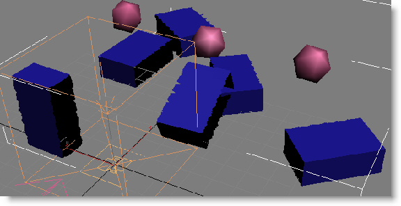
If you prefer a straighter edge, try reducing the Edge Split Precision
 Relative% value.
 You might notice that the pieces don't seem very solid, as you can see through the inside surfaces. This can be remedied with a standard modifier.
- Apply a Shell modifier to the box, above the Particle Skinner modifier, and set the Inner Amount to 2.0 and the Outer Amount to 1.0.
Now when you play the animation, the pieces look more realistic.
Tip: If you want to render the animation, first set the Render operator in the PF Source event to Type=Phantom, so the particles don't render.
Summary
This tutorial, as long as it was, gave you but a tiny taste of the many capabilities of the Particle Flow simulation tools. We recommend that you experiment with the scenes you've created, changing parameters, using different types and quantities of particles, and so on.