This section describes how to create the first profile toolpath, which applies to the offset vector and to the vector text. Use this toolpath to carve-out small amounts of material for the plaque's border and the Reception text using a 5 mm end-mill tool.
To create the first toolpath:
- In the Project Tree, select the Toolpaths item. The Toolpaths panel is displayed.
- In the
2D Toolpaths area, click the
Create Profile Toolpath
 button. The
2D Profiling panel is displayed.
button. The
2D Profiling panel is displayed.
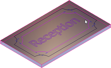
- Select the vectors to be machined:
- In the Profile Type & Vector Association area, select Outside and Selected vectors in the Profile lists.
- Hold the
Shift key, then select the vector text and the offset vector. The vectors are displayed in purple:
 Tip: Click the Isometric View 1
 button on the
3D View toolbar to display this view.
button on the
3D View toolbar to display this view.
- Specify the tool for profile machining the selected vectors:
- In the Profiling Tool area, click the Click to Select control bar. The Tool Database dialog is displayed.
- In the Tools & Groups area, select Tools & Groups > Metric Tools > Wood or Plastic > Roughing and 2D Finishing > End Mill 5 mm. The tool's details are displayed in the Tool / Group Description area.
- Click Select. The dialog closes.
- Specify the settings for the toolpath:
- In the Profile Type & Vector Association area, enter an Allowance of 0 to specify the distance between the tool and the selected vectors.
- In the Cutting Depths area, enter a Start depth of 0 to specify the depth from the material's surface at which the tool begins machining.
- Enter a Finish depth of 10 to specify the depth from the material's surface at which the tool stops machining.
- Enter a Tolerance of 0.01 to specify how closely the tool follows the selected vectors.
- In the Profiling Tool area, select Climb in the Cutting direction list to specify climb milling instead of conventional milling. Climb milling means the tool's cutter rotates in the same direction as the feed motion. This often provides a better finish and prolongs the life of the tool.
- In the Options area, click the Safe Z and Home control bar to display its settings.
- Enter a Safe Z value of 10 to specify the height above the material's surface at which the tool can make rapid moves between toolpath segments.
- Enter a Home X value of 0, a Home Y value of 0, and a Home Z value of 10 to specify the tool's start and end position.
- Specify the dimensions of the sheet of material from which the plaque is to be machined:
- In the
Options area, click the
Click to Define Material control bar. The
Material Setup dialog is displayed.
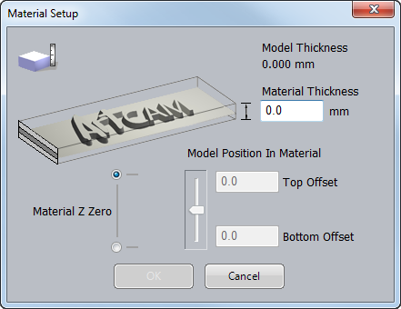
- Enter a Material Thickness of 20.
- Click OK. The dialog closes and a transparent sheet of material is displayed in the 3D view.
- In the
Options area, click the
Click to Define Material control bar. The
Material Setup dialog is displayed.
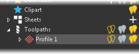
- Enter a Name of Profile 1 for the toolpath.
- Click
Calculate Now.
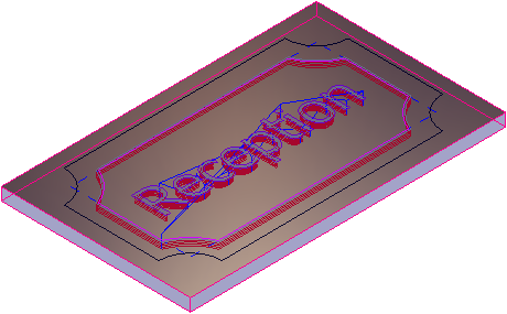
ArtCAM calculates the toolpath and adds a Profile 1 item under the Toolpaths item in the Project Tree:
The toolpath (red) and rapid moves (blue) are displayed:
- In the Project Tree, click the lightbulb
 icon next to the
Profile 1 item to hide the toolpath. The icon changes to
icon next to the
Profile 1 item to hide the toolpath. The icon changes to
 .
.
- Click the 3D view to deselect the selected vectors.