When you click Calculate in the 2D Machining Wizard, ArtCAM begins by calculating the required number of sheets for each different type of material previously identified from the text file. The resulting sheets adopt the name of the material found in the text file.
The vector data contained in the .dxf files referenced within the text file is then nested across these sheets. The data within the text file determines what vector artwork is intended for which sheet.
The nesting clearance previously defined is applied during the nesting calculation process.
Where accumulated vector data found between the .dxf files cannot be nested on a single sheet, subsequent sheets are created as necessary and are numbered sequentially. For example, if two sheets of 3/4 Ply are needed to host all of the vector artwork embedded within thirteen of the .dxf files, these are named 3/4 Ply_Sheet1 and 3/4 Ply_Sheet2 respectively.
The 2D Machining Wizard then creates new vector layers in the model according to the layer information within the .dxf files. The nested vector artwork remains on the same layer as that which was originally created as part of the .dxf file.
When all of the vector data has been assigned to appropriate sheets and layers, the 2D Machining Wizard loads the toolpath template and begins the toolpath calculation process.
A message reading "Creating toolpaths for each sheet..." is then displayed in the Message Area.
The 2D Machining Wizard reads the name of a vector layer and then searches for exactly the same text in all of the toolpath names that originate from the toolpath template. The information is stored within brackets as part of the toolpath name. For example, the vector layer named Panel_0P2500 is clearly referenced in the toolpath named 1/4 Ply_Sheet1_Profile (Panel_0P2500).
Where the name of a vector layer matches the text within the brackets in the toolpath name, the 2D Machining Wizard applies the toolpath settings in the template to the artwork on that layer. This process is repeated until toolpath settings have been applied to all of the vector artwork drawn across the layers.
A message reading "Calculating toolpaths..." is then displayed in the Message Area. The 2D Machining Wizard calculates all of the toolpaths in sequence as part of a single batch:
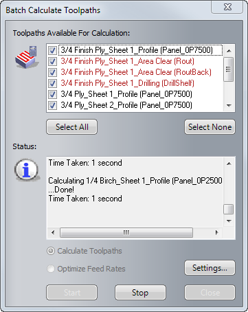
Calculated toolpaths are listed in the Toolpaths Available For Calculation window in black, while uncalculated toolpaths are listed in red.
All of the messages displayed in the Status area of the Batch Calculate Toolpaths dialog are repeated in the Message Area of the 2D Machining Wizard panel.
A message reading "Writing GCode..." is displayed in the Message Area. The 2D Machining Wizard outputs the toolpath files for your chosen post-processors to the selected toolpath output folder.
A message reading "Finished" is displayed in the Message Area.
The nested panel vector artwork is shown in the 2D view along with a preview of all of the toolpaths needed to machine this, and the new vector layers, sheets and toolpaths are listed in the Project Tree.
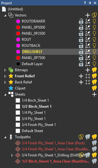
The vector artwork found within the Drawing Interchange Format (.dxf) files is nested across six sheets. Each sheet represents an actual sheet of material required for the job and adopts the name of the different types of materials identified in the text file during the calculation process.
You can control which sheet of nested vector artwork is shown in the 2D view by clicking on its name in the project tree. Only one sheet can be viewed at any time, although it is possible to preview the contents of all sheets. You can only edit the vector artwork drawn on the sheet that is currently selected.
It may help to visualize the active sheet as the CNC table bed and the remaining sheets as the material within your workshop.