You can make several copies of a selected calculated toolpath in a circular pattern, using a specified centre of rotation.
In the example below, a rotate copy of a merged toolpath is shown:
|
Before
|
After
|
To rotate copy a toolpath:
- In the
Toolpath Operations area of the
Toolpaths panel, click the
Copy Toolpaths
 button to display the
Toolpath Copy panel.
button to display the
Toolpath Copy panel.
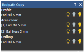
A list of all calculated toolpaths is displayed at the top of the panel.
- Select Rotate Copy to display the rotate copy options.
- Select which of the toolpaths you want to rotate copy:
If you want to rotate copy a toolpath, it must be visible in the 3D view. Turn off the visibility of all toolpaths other than the one you are copying.
Note: If a toolpath makes use of more than one tool, click the toolpath name to rotate copy all of its machining passes, or an individual tool name if you want to rotate copy a specific machining pass.In this example, the 3D view light bulbs for all three toolpaths are turned on, meaning that all of the listed toolpaths are visible:
- Use either of the following methods to specify the point around which you want to rotate copy the selected toolpaths:
- In the Rotation Centre X and Rotation Centre Y boxes, enter the X and Y coordinates of the origin of rotation.
- Select Pick Centre with Mouse. In the 2D view, move the cursor to the position in the model that you want to use as the origin of rotation, and then click to select. Its co-ordinates are displayed in the Rotation Centre X and Rotation Centre Y boxes.
- Specify the angle of rotation that you want to use:
- If you want to rotate each subsequent copy of the selected toolpaths by a specific angle, select
Incremental, and then, in the
degrees box, enter the angle of rotation.
Enter a positive value to rotate the selected toolpaths clockwise. Enter a negative value to rotate the selected toolpaths counter-clockwise.
- If you want to rotate each copy of the selected toolpaths evenly within the specified angle, select Total, and then, in the degrees box, enter the angle.
- If you want to rotate each subsequent copy of the selected toolpaths by a specific angle, select
Incremental, and then, in the
degrees box, enter the angle of rotation.
- In the Number of Objects box, enter the number of copies that you want to create.
- If you want to merge all of the selected toolpaths and their associated circular pattern of copies into a single toolpath:
- Prioritize the toolpaths using
 and
and
 when a toolpath is selected. The order in which the toolpaths are listed on the panel reflects the machining order of the toolpaths that make up the merged toolpath. The toolpath at the top of the list is the first to be machined, and so on.
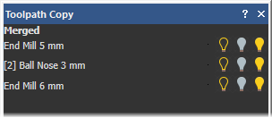
- Select Merge Results. This displays the Name box.
- In the Name box, enter a name for the new merged toolpath.
Note: If you do not name the toolpath, the Merged label is used by default.In the example, the merged toolpath is given the default name.
- Prioritize the toolpaths using
- Click
Apply to create the new circular pattern of toolpaths.
In this example, the pattern of toolpaths is displayed in the 2D view as shown below:
Before

After
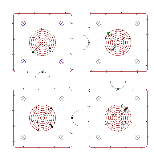
The Merged toolpath replaces all of the individual toolpaths previously listed on the panel: