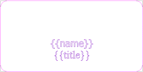
To create multiple plates:
- Create the vector artwork representing the overall shape of the plate to which you want to add data.

- Use the
Text Tool to enter the names of the variables that you want to use on each plate in vector text. These must be enclosed in double curly braces.
In this example, the template vector artwork for the plate layout is now shown as follows:

- Create the toolpath that you want to use to machine the plates that you are creating.
- Select all of the vector artwork representing the template for the plate layout.
- Select the preview of the toolpath that you have calculated.
- Select
Vector > Multi-Plate or click the
Multi-Plate Tool
 button. The first page of the
Multi-Plate Tool panel is displayed.
Note: If you click the Multi-Plate Tool button without first selecting the vector artwork representing the template for the plate layout, a message dialog is displayed asking you to select the vector artwork.
 - Click Set Template to set the selected vector artwork as the template for the plate layout.
- In the
Import Text File Data area, click
Load Data to display the
Load Data dialog.
Note: You can open data saved as a .txt or .csv file only.
- Select the folder containing the text file you want to open, and click the file name. The name is displayed in the File Name area.
- Click Open to display the Text File Import dialog. A preview of the data within the text file is displayed in the dialog. You can control how the data is used in the multi-plate.
- Click OK to import the data.
- In the
Sheet Layout area, use the settings to set the material dimensions and the number of plates you want to create.
The number of sheets is displayed on the panel. The number depends on the size of the material and the number of plates.
- In the Plate Layout area, use the settings to control the appearance of the plates created in a sheet.
- Click
Next
 to display the second page of settings.
- Click the Preview For Sheet list, followed by the sheet you want to preview. The number marked by a red square
 indicates the currently selected plate.
- The Variables Section area contains a list for each variable you created as vector text (enclosed in curly braces), as part of the template vector artwork. Select an option from each list to specify the properties of each variable.
- In the
Plate Values area, you can edit the variables that will be created as vector text on each plate on the sheet. Select the plate for which you want to edit the variables.
With the plate selected, you can type in each box for each variable associated with the plate. For example, name, age and address. Click Update to confirm any changes you make to the variables.
- Click
Create Plates to create the sheet of plates. The data used for the selected variables is displayed as vector text on each plate in the same position.
The vector text created is constrained by default to ensure the text fits within the vector representing the plate. Each sheet of plates is created separately in the model. Each sheet is named PlateSheet by default, numbered sequentially, and assigned the colour black. Each sheet of plates is listed on the Vector Layers panel. The last sheet is displayed by default.
You can control which sheet of plates is shown in the 2D view by clicking to select the name of the specific PlateSheet you want to view from the Active Sheet list. You can only view one sheet of plates at a time. You can only edit the vector artwork on the active sheet.
In the 2D view, the arrangement of the rows and columns of sheets shown varies according to the most economical use of the available space.
After the vector artwork for the plates has been created, the Create Toolpaths button is displayed at the bottom of the panel.
- In the 2D view, ensure all the vector artwork and the toolpath preview shown are selected.
- Click
Create Toolpaths to calculate the toolpaths needed to machine the plates.
A separate toolpath is calculated for each sheet in the model. This enables you to save each toolpaths associated with each sheet as a separate toolpath file.
 icon to return to the first page of settings on the
Multi-Plate Tool panel.