When you have created a toolpath, you can adjust certain machining parameters without recalculating the toolpath. You can adjust parameters which apply to the parent toolpath group, and parameters which apply to the individual child toolpaths.
To adjust the machining parameters for a parent toolpath group:
- In the Project panel, click the
 icon to expand the
  Toolpaths item.
 - Select the parent toolpath group whose parameters you want to adjust. This displays its panel below the splitter bar.
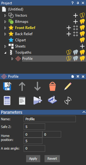
- You can now adjust the following machining parameters:
- Name — Enter a name for the parent toolpath group.
- Safe Z — Enter a value for the height at which the tool makes rapid movements between toolpath segments.
- Home position — Enter a value for the Home position of the tool.
- A axis angle — If your CNC machine has a rotary axis, it is possible to let the machine turn the model for you. ArtCAM allows you to output a single toolpath containing both the front and back toolpaths together. The back toolpath is preceded by a rotary move that turns the material block into position before cutting.
If you want to use automatic indexing, in the A axis angle box, enter the angle of the rotated toolpath. The angle is appended to the name of the toolpath, and is shown in brackets. You must also output the toolpaths together using a post processor that supports indexing. For example, the Model Master Indexer.
- Click Apply.
Note: If you want to recover the parameters used prior to your last click on the Apply button, click the Revert button.
To adjust the machining parameters for a child toolpath:
- In the Project panel, click the icon to expand the Toolpaths item.
- Select the parent toolpath group which contains the child toolpath whose parameters you want to adjust.
- Select the child toolpath you want to adjust. This displays its panel below the splitter bar.
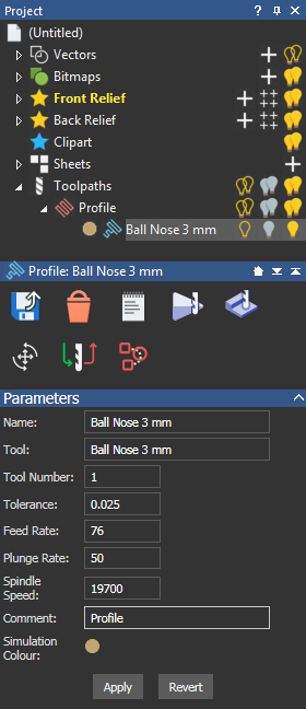
- You can now adjust the following machining parameters:
- Name — Enter a name for the child toolpath.
- Tool Number — Enter the number you want to assign to the selected tool. This number should correspond with the position of the tool in the CNC machine's tool changer.
- Feed Rate — Specify the rate at which the tool moves in relation to the material block to change the feed rate of the selected tool.
- Plunge Rate — Specify the rate at which the tool moves in the Z direction and plunges into the material block to change the plunge rate of the selected tool.
- Spindle Speed — Specify the rotational speed of the spindle. The spindle is the part of the machine tool that rotates during operation. On a mill it holds the tool in position. On a lathe it holds the material block.
- Comment — Enter a comment for the machinist. This comment appears in the post-processed G-code.
- Simulation Colour— Click the colour swatch to display the Colour dialog and select the colour for the simulated toolpath.
- Click the Apply button.Note: If you want to recover the parameters used prior to your last click on the Apply button, click the Revert button.