When creating a shank, an ArtCAM model is created as part of the project according to the settings you define.
To create a model using a shank:
- Select File > New > Project. ArtCAM displays the project screen.
- In the
Project panel, click the
Models
 item in the Project Tree. This displays the
Models panel below the splitter bar.
item in the Project Tree. This displays the
Models panel below the splitter bar.
- In the
New Shanks area, click the button representing the shank you want to create. The shank's panel is displayed, for example:
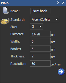
- Enter a name for the empty component in the
Name box.
Note: Each shank is given a different default name.
- If you are creating any of the available shanks:
- Click the Standard list, then select the option for the national standard system in which you want to create the shank.
- If you have selected anything other than the Custom option, click the Size list followed by the size of shank that you want to create.
- If you have selected the Custom option, specify the diameter of the shank in the Diameter box.
- Specify the border that you want to apply around the shank in the Border box.
- Specify the resolution of the model in the Resolution box.
- If you are creating any of the shanks other than the
Tapered Round,
Tapered Square or
Tapered Knife Edge:
- Specify the width of the shank in the Width box.
- Specify the distance between the inner and outer diameter of the shank in the Thickness box.
- If you are creating any of the shanks other than the
Tapered Round,
Tapered Square or
Tapered Knife Edge:
- Specify the width of the shank in the Width box.
- Specify the distance between the inner and outer diameter of the shank in the Thickness box.
- If you are creating a
Tapered Round,
Tapered Square or
Tapered Knife Edge shank:
- Click
 to display the next group of settings.
- Specify the thickness of the top of the tapered shank in the Top Thickness box.
- Specify the thickness of the bottom of the tapered shank in the Bottom Thickness box.
- Specify the width at the top of the tapered shank in the Top Width box.
- Specify the width at the bottom of the tapered shank in the Bottom Width box.
- Click
to create the shank according to your settings.
A model
 is created beneath the
Models
item in the Project Tree. The model is named according to that specified when defining the shank's settings. For example,
TaperedKnifeEdgeShank.
is created beneath the
Models
item in the Project Tree. The model is named according to that specified when defining the shank's settings. For example,
TaperedKnifeEdgeShank.
ArtCAM calculates the necessary dimensions of the model according to the settings associated with the shank. The resulting model is always in metric measurements.
The resulting model contains:
- Two locked reference guideline vectors in the model area; one marking the vertical centreline and the other marking the horizontal centreline. This artwork is hosted on the Reference Lines vector layer.
- Two locked concentric circular vectors below the model area. This artwork is drawn on the Reference Silhouette vector layer.
- A circular vector drawn about the outer circle below the model area; used as a ring silhouette if the shank is rebuilt. This artwork is drawn on the Default Layer vector layer.
- Two parallel horizontal linear vectors drawn in the model area; both used as drive rails when the shank is calculated. This artwork is drawn on the Default Layer vector layer.
- Two profile vectors drawn in the model area; both used as cross-sections when the shank is calculated. This artwork is drawn on the Default Layer vector layer.
Note: Both the Gem Tools and Rotary Relief Tools areas are displayed on the Assistant's Home page.The vector artwork drawn on the Default Layer vector layer is essentially used to calculate a two-rail swept ring shape.
In the Project Tree, a Rotary Relief
 is associated with the model. The rotary relief is shown in the 3D view by default.
- Click
- Click
to create the shank according to your settings.
A model
is created beneath the
Models
item in the Project Tree. The model is named according to that specified when defining the shank's settings. For example,
TaperedKnifeEdgeShank.
ArtCAM calculates the necessary dimensions of the model according to the settings associated with the shank. The resulting model is always in metric measurements.
The resulting model contains:
- Two locked reference guideline vectors in the model area; one marking the vertical centreline and the other marking the horizontal centreline. This artwork is hosted on the Reference Lines vector layer.
- Two locked concentric circular vectors below the model area. This artwork is drawn on the Reference Silhouette vector layer.
- A circular vector drawn about the outer circle below the model area; used as a ring silhouette if the shank is rebuilt. This artwork is drawn on the Default Layer vector layer.
- Two parallel horizontal linear vectors drawn in the model area; both used as drive rails when the shank is calculated. This artwork is drawn on the Default Layer vector layer.
- Two profile vectors drawn in the model area; both used as cross-sections when the shank is calculated. This artwork is drawn on the Default Layer vector layer.
Note: Both the Gem Tools and Rotary Relief Tools areas are displayed on the Assistant's Home page.The vector artwork drawn on the Default Layer vector layer is essentially used to calculate a two-rail swept ring shape.
In the Project Tree, a Rotary Relief
is associated with the model. The rotary relief is shown in the 3D view by default.
- To adjust the overall shape of the shank:
- Edit the default vector artwork used to create the shank.
- Click
 . The new shank shape is calculated using the edited vector artwork.
Note: Do not add any decorative detail to the shank before clicking, otherwise it will be lost during the recalculation process.
. The new shank shape is calculated using the edited vector artwork.
Note: Do not add any decorative detail to the shank before clicking, otherwise it will be lost during the recalculation process.
If you do not want to change the shape of the shank, go to the next step.
Note: If you click , the current model is closed. The model icon
 in the Project Tree indicates this.
Note: Although you can edit the shape of the model's drive rails, cross-sections, and ring silhouette, you cannot replace them with different vectors. You can reposition any of the vectors used to create the shank, although moving the ring silhouette may cause unwanted results. - Click
 to close the panel. The model
beneath the
Models
folder in the Project Tree remains open.
to close the panel. The model
beneath the
Models
folder in the Project Tree remains open.
If you are creating a Plain, Square, or Knife Edge shank, the Base Height is equal to the Thickness of the shank.
If you are creating a Tapered Round, Tapered Square, or Tapered Knife Edge shank, the Base Height is equal to the average of the Top Thickness and Bottom Thickness.