The Parameters and Drill Bank Configuration areas contain the following settings:
- Feeds and Speeds — If you want to amend the machining parameters for the drill bank, click the
Feeds and Speeds control bar to display the
Feed Rate,
Plunge Rate,
Spindle, and
Tool Number boxes.
- Feed Rate — Enter the feed rate of the drill bank.
- Plunge Rate — Enter the plunge rate of the drill bank.
- Spindle — Enter the rotational speed of the spindle. The spindle is the part of the drill bank that rotates during operation. On a mill it holds the tool in position. On a lathe it holds the block of material.
- Tool Number — Enter the position of the drill bank within the CNC machine's tool changer.
- Drill Bank Configuration — If you want to change the configuration of the drill bank, click
Advanced to display the
Size,
Center,
Origin Drill, and
Pitch boxes.
- Size — Enter the number of drills in the bank along the X axis in the W box, and the number of drills along the Y-axis in the H box.
- Center — Enter the X and Y coordinates of the zero drill in the X and Y boxes.
- Origin Drill — Enter the X and Y coordinates of the origin drill in the X and Y boxes. The origin drill is shown in green in the Drill Diagram (View Down Z) area of the panel.
- Pitch — Enter the distance between each drill in the bank. The default distance of 32 mm is the European Standard.
When you have made your changes, click Update Config to update the drill bank configuration.
Note: The drill bank configuration Advanced settings should only be updated by an expert. An incorrect configuration could cause machining errors. - Drill Diagram (view down Z) — You can adjust the diameter of any of the tools in the default drill bank layout.
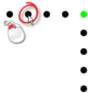
- Click the circle in the Drill Diagram (View Down Z) area which represents the position of the tool in the drill bank. Its diameter is displayed in the
Diameter box, and its number is displayed in the
Number box.
For example, if you click the black circle representing the drill tool second from left in the default drill diagram, 5 is displayed in the Diameter box, and 2 is displayed in the Number box.
 Note: You cannot edit the tool number associated with any tool in the drill bank unless the Advanced settings are displayed on the page.
 - Enter the new diameter of the selected tool in the Diameter box.
- Click the
Update Drill button. The size of the circle is adjusted according to the diameter that you have entered.
For example, if you enter 15 in the Diameter box, the black circle representing the drill tool second from left in the default drill diagram is now displayed as follows:

- Click the circle in the Drill Diagram (View Down Z) area which represents the position of the tool in the drill bank. Its diameter is displayed in the
Diameter box, and its number is displayed in the
Number box.