The
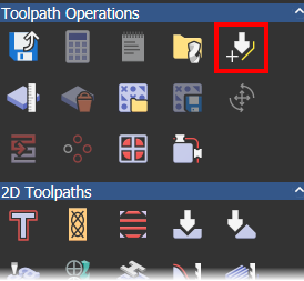
Create Custom Form Tool
 button is available from the
Toolpath Operations area of the
Toolpaths panel. You can use this to create form tools that match the ones you have in your tool room. This enables you to simulate toolpaths more accurately, and can reduce simulation time because you no longer have to try to match a single tool with a mixture of tools from the tool database.
button is available from the
Toolpath Operations area of the
Toolpaths panel. You can use this to create form tools that match the ones you have in your tool room. This enables you to simulate toolpaths more accurately, and can reduce simulation time because you no longer have to try to match a single tool with a mixture of tools from the tool database.
Before you click
, you must first import or create an open vector to define the half-profile of the form tool. This vector is revolved to create the tool, and the diameter of the tool is taken from the widest point of the profile. The custom form tool cannot be scaled after it is created so you must ensure the vector exactly matches the dimensions of your tool.
When you click
, the
Edit Tool dialog is displayed. Use this dialog to set the parameters for your tool.
Your custom form tool is added to the Tool Database and can subsequently be edited in the same way as the standard tools, except you cannot change the diameter.
To create a custom tool:
- Sketch or import an open vector that defines the exact dimensions of your tool's half-profile. This vector is revolved to create the tool.

- Ensure the vector is selected, then in the
Toolpath Operations area of the
Toolpath panel, click
to display the
Edit Tool dialog.
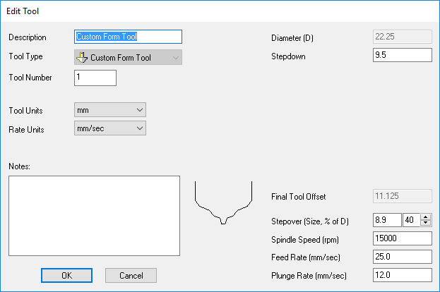
The dialog displays the profile of the tool you are creating, and contains boxes in which to enter details about the tool.
- Enter your tool's parameters.
- Click
OK. The
Tool Database dialog is displayed.

Your custom tool is added to the bottom of the tool tree.
Tip: You can drag the tool to move it to a new location in the tool tree. - Click OK to close the dialog.