The rest-machining toolpath enables you to find all of the areas of the composite relief that cannot be machined based on one tool size, and then machine only these areas with another, smaller tool.
ArtCAM compares the composite relief representing a finished model with simulated toolpath data, and then creates vectors in the shape of the areas of the composite relief that these toolpaths fail to machine. A Machine Relief toolpath strategy can then be applied to some or all of these vectors to improve the overall surface finish of the manufactured model.
To rest machine the composite relief:
- In the Project Tree, click the
 Toolpaths item. This displays the
Toolpaths panel below the splitter bar.
Toolpaths item. This displays the
Toolpaths panel below the splitter bar.
- In the
3D Toolpaths area of the
Toolpath panel, click the
Create 3D Rest Machining Toolpath
 button to display the
3D Rest Machining panel.
button to display the
3D Rest Machining panel.
- In the
Area To Rest Machine area, select the area of the composite relief that you want to machine:
- Complete relief — This option instructs
ArtCAM to distinguish the differences between the toolpath simulation and the composite relief, and then identify them for machining purposes.
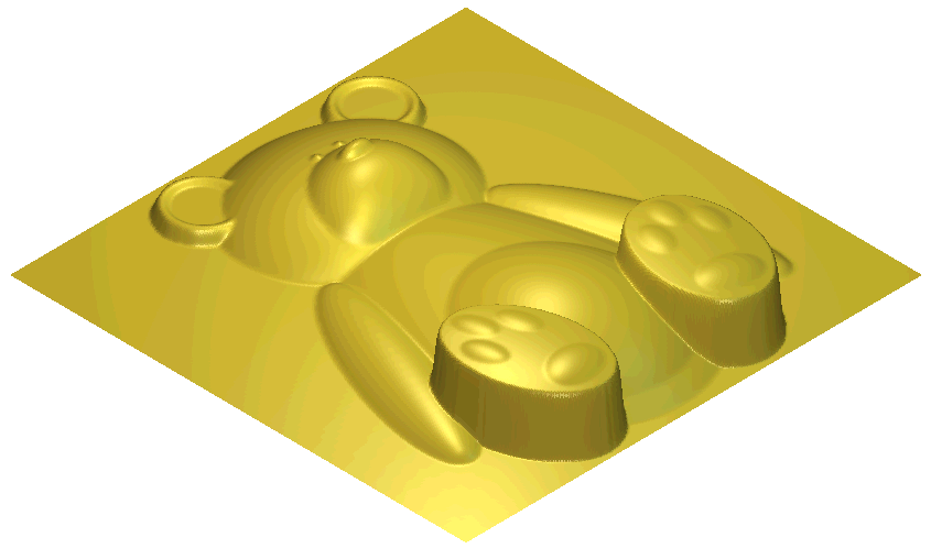
For example, a teddy bear composite relief looks as follows:
- Area Under Selected Vectors — This option instructs ArtCAM to distinguish the differences between the toolpath simulation and the composite relief underlying the currently selected vectors, and then identify them for machining purposes.
- Complete relief — This option instructs
ArtCAM to distinguish the differences between the toolpath simulation and the composite relief, and then identify them for machining purposes.
- In the
Identify Areas Already Machined By area, click to select the method you want to use to identify the unmachined areas of the composite relief:
- Simulating All Toolpaths — This option instructs
ArtCAM to simulate all calculated toolpaths and then compare the result against the composite relief to identify its unmachined areas.
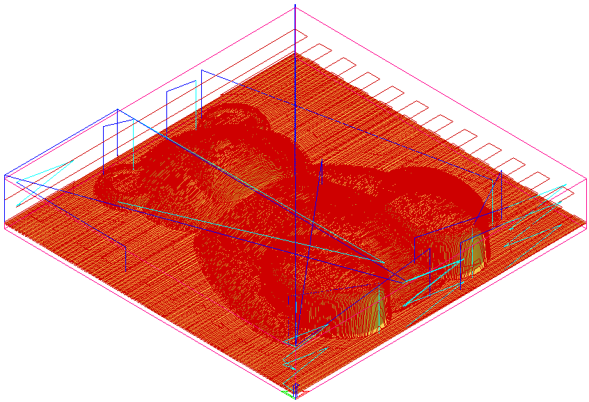
In the teddy bear example, all three toolpaths used to machine the teddy bear composite relief are simulated. These are displayed in the 3D view as follows:
- Simulating the Last Toolpath — This option simulates the last calculated toolpath and then creates a model of the unmachined areas of the composite relief.
- Using the Current Simulation — This option uses the existing toolpath simulation shown in the 3D view to identify the unmachined areas of the composite relief.
- Simulating All Toolpaths — This option instructs
ArtCAM to simulate all calculated toolpaths and then compare the result against the composite relief to identify its unmachined areas.
- After simulating a toolpath, you may notice small areas of material, or cusps, remain in the model as a consequence of a machining tool's geometry or the stepover used between machining passes. In the Cusp Tolerance box, enter the height at which you want ArtCAM to ignore any existing cusps as areas of the model that require additional machining.
- In the
Layer for rest boundaries box, enter the name of the vector layer in which you want
ArtCAM to create the vectors representing the unmachined areas of the composite relief.
Note: If the Layer for rest boundaries box is empty, the vectors are created on the vector layer currently selected.
- Click Create Boundaries to calculate the unmachined areas of the composite relief from the toolpath simulation, and then create vectors representing these areas. The simulated toolpaths are displayed in the 3D view.
- Press the
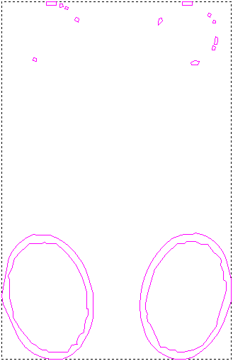
F2 key to display the vectors representing the unmachined areas of the composite relief in the 2D view.
In the teddy bear example, ArtCAM identifies unmachined areas around the feet and ears in the teddy bear composite relief.
- Close the panel.
You are now ready to apply a Machine Relief toolpath to the vectors representing the unmachined areas. This toolpath will improve the overall surface finish of the composite relief during the manufacturing process.