Use the grid-creator toolpath to create a grid of intersecting horizontal and vertical linear vectors and machine along them. This is a quick method of producing rectangular pieces with an equivalent size.
Click the
Open the
Grid Creator
 button on the
Toolpaths panel to display the
Grid Creator panel. The following settings are available:
button on the
Toolpaths panel to display the
Grid Creator panel. The following settings are available:
- Grid Dimensions — Specify the grid dimensions.
- Grid Name — Enter a name for the grid.
- Grid Vectors — Create the grid lines.
- Grid Centerline Toolpath — Define the material block, select a tool, and set the machine safe Z distance.
- Calculate Later — Click this button if you want to calculate the toolpath at a later time either by itself or as part of a batch. The toolpath is added to the Project Tree under the Toolpaths item, but is red to indicate it has not been calculated.
- Calculate Now — Click this button to calculate the toolpath now. A progress bar is displayed in the Status Bar area during calculation, then the toolpath is added to the Project Tree under the Toolpaths item. It is black to indicate it has been calculated. A wireframe representation of calculated toolpath is displayed.
Note: You can edit a toolpath's settings before or after it has been calculated.
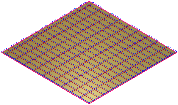
The calculated grid toolpath might look something like this:
After you have calculated the toolpath, you can simulate it.
Note: The availability of this feature is license dependent.