To create a model using any blank other than a Rotary Flush:
- Select File > New > Project. ArtCAM displays the project screen.
- In the
Project panel, click the
Models
 item in the Project Tree. This displays the
Models panel below the splitter bar.
item in the Project Tree. This displays the
Models panel below the splitter bar.
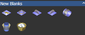
- In the
New Blanks area of the
Models panel, click the button representing the component you want to create.
This displays the selected blank's panel, for example:
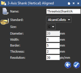
- Enter the name you want to give to the empty component in the
Name box.
Note: Each component is given a different default name.
- If you are creating any blank other than a
3-Axis Flat or
Rotary Setting, click the
Standard list, then select the option for the national standard system in which you want to create the empty component.
- If you have selected anything other than Custom, click the Size list, then select the size of empty component that you want to create.
- If you have selected Custom, or are creating a Rotary Setting blank, specify the diameter of the empty component in the Diameter box.
- If you are creating any blank other than a
Rotary Setting:
- Specify the width of the empty component in the Width box.
- Specify the resolution of the model in the Resolution box.
If you are creating any blank other than a 3-Axis Flat:
- Specify the border you want to apply around the empty component in the Border box.
- Specify the distance between the inner and outer diameter of the empty component in the Thickness box.
If you are creating a 3-Axis Flat or Rotary Setting blank:
- Specify the height of the empty component in the Height box.
- Click
 to close the panel and create the
ArtCAM model for the component.
to close the panel and create the
ArtCAM model for the component.
An open model
 is shown beneath the
Models
item in the Project Tree. The model is named according to that given when defining the blank's settings. For example,
ThreeAxisShank.
is shown beneath the
Models
item in the Project Tree. The model is named according to that given when defining the blank's settings. For example,
ThreeAxisShank.
ArtCAM calculates the necessary dimensions of the model according to the settings associated with the chosen blank. The resulting model is always in metric measurements.
If you have created a 3-Axis Flat blank:
- A model named ThreeAxisFlat by default is created.
- Two locked reference guideline vectors are created in the model area. This artwork is hosted on the Reference Lines vector layer.
If you have created a 3-Axis Shank blank:
- A model named ThreeAxisShank by default is created.
- Two locked reference guideline vectors are created in the model area; one marking the vertical centreline and the other marking the horizontal centreline. This artwork is hosted on the Reference Lines vector layer.
- Two locked concentric circular vectors representing the inner and outer diameter of the ring, offset by the previously defined Thickness, are created in the model area. This artwork is hosted on the Reference Silhouette vector layer.
If you have created a 3-Axis Shank (Vertical) Aligned blank:
- A model named ThreeAxisShankVA by default is created.
- Two locked reference guideline vectors are created in the model area; one marking the vertical centreline and the other marking the horizontal centreline. This artwork is hosted on the Reference Lines vector layer.
- Two locked vertical rectangular vectors representing the inner and outer diameter of the ring, offset by the previously defined Thickness, are created in the model area. This artwork is hosted on the Reference Silhouette vector layer.
If you have created a 3-Axis Shank (Vertical) blank:
- A model named ThreeAxisShankV by default is created.
- Two locked reference guideline vectors are created in the model area; one marking the vertical centreline and the other marking the horizontal centreline. This artwork is hosted on the Reference Lines vector layer.
- Two locked horizontal rectangular vectors representing the inner and outer diameter of the ring, offset by the previously defined Thickness, are created in the model area. This artwork is hosted on the Reference Silhouette vector layer.
If you have created a Rotary Axis Shank blank:
- A model named RotaryAxisShank by default is created.
- Two locked reference guideline vectors are created in the model area; one marking the vertical centreline and the other marking the horizontal centreline. This artwork is hosted on the Reference Lines vector layer.
- Two locked concentric circular vectors representing the inner and outer diameter of the ring, offset by the previously defined Thickness, are created below the model area. This artwork is hosted on the Reference Silhouette vector layer.
If you have created a Rotary Setting blank:
- A model named RotarySetting by default is created.
- Two locked reference guideline vectors are created in the model area; one marking the vertical centreline and the other marking the horizontal centreline. This artwork is hosted on the Reference Lines vector layer.
- Two locked concentric circular vectors representing the inner and outer diameter of the ring, offset by the previously defined Thickness, are created below the model area. This artwork is drawn on the Reference Silhouette vector layer.