You can simulate calculated toolpaths in the 3D view. This enables you to envision the machining passes used to create your finished piece.
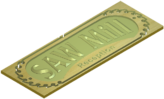
In the 2D view, you can assign different colours to each calculated toolpath to show more information about a toolpath than the default view, for example:

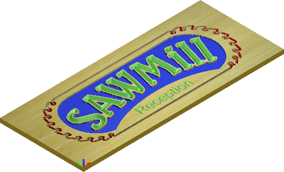
In the 3D view, you can simulate calculated 2D or 3D toolpaths in a simulation block. You can control how the toolpath simulation is rendered and apply a depth colour to all areas of the simulation below the Z zero height. This enables you to clearly envision the finished piece. For example, the same simulated 2D toolpaths shown above might look something like this:
In the 3D view, you can simulate calculated toolpaths using different colours to show which areas are cut by each tool, for example:
You can simulate calculated toolpaths in the 3D view in four different ways. You can simulate:
- a specific toolpath;
- a particular tool used in a toolpath;
- a particular region of a toolpath, specified by a selected vector;
- all toolpaths in succession.
You can choose between three toolpath simulation methods:
- Simulate All Toolpaths — Display a simulation block and quickly simulate all of your toolpaths.
- Simulate Toolpath — Display a simulation block and quickly simulate a specific toolpath or tool used as part of a toolpath.
- Simulation Control toolbar — Display a simulation block and a toolbar you can use to simulate your toolpaths in greater detail and with far greater control.
The simulation tools are available from:
- The
Project panel, using the context menu and tools associated with the
 Toolpaths, parent toolpath
 and child toolpath
 items in the Project Tree.
- The Toolpath > Simulation submenu.
- The Simulation toolbar.
- The
Simulation panel, which is displayed when you select the
 Simulation item in the Project Tree. The
Simulation item does not appear in the Project Tree until you have run a simulation.
Simulation item in the Project Tree. The
Simulation item does not appear in the Project Tree until you have run a simulation.