AutoCAD Civil 3D can calculate values from the geometric definition of a vertical curve, PVI information, as well as object and eye height.
These values are derived from empirical equations and do not use design speed.
For a crest curve, passing and stopping sight distances are used because a curve peak can obstruct a driver's view of the roadway surface or another object.
Passing and stopping sight distances are not used for a sag curve because there is no curve peak to obstruct a driver's view of the roadway surface or another object. In daylight, with good visibility, the driver has a full view of the road on a sag curve. At nighttime, however, the driver can see only as far as the distance of the headlight beam. To design a sag curve, you can use headlight sight distance.
You can display these properties in AutoCAD Civil 3D 2018 using the Text Component Editor. In Toolspace, on the Settings tab, expand Profile  Label Styles
  Curve. Double-click the default Crest and Sag label style. Click the Layout tab. Under Component Name, select an item such as BVC. On the Text Component Editor, click the drop-down arrow under Properties to display the list of available properties. Scroll down to see properties such as Headlight Sight Distance, Passing Sight Distance, and so on.
Creating Crest Curves Based on Passing and Stopping Sight Distances
Passing sight distance is the distance necessary for a driver to see an oncoming vehicle in order to determine if there is enough distance to allow a passing lane. The passing sight distance is not used often in crest curve design because the curve length needed to meet the passing sight criteria is usually prohibitive.
Stopping sight distance, a widely used criterion for determining curve length, is the distance necessary for a driver to see a hazard on the roadway surface. Governmental guidelines determine the sight distance for passing and stopping requirements.
The following equations calculate crest curve lengths using the passing and stopping sight distances.
where:
L = Length of vertical curve in feet (or meters)
S = Sight distance in feet (or meters)
A = Algebraic difference in grade percent (%)
h1 = Height of observer's eye above roadway surface in feet (or meters)
h2 = Height of object above roadway surface in feet (or meters)
The following equation solves for L when S is less than L:

The following equation solves for S when S is less than L:

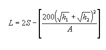
The following equation solves for L when S is greater than or equal to L:

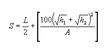
The following equation solves for S when S is greater than or equal to L:

Creating Sag Curves Based on Headlight Sight Distance
At nighttime, a vehicle's headlight beams define the sight distance. A sag curve intercepts a headlight beam on the roadway surface and limits the length of the beam. Headlight sight distance measures the top of the headlight beam above the pavement and the maximum headlight angle to determine curve length. The height of the driver's eye is also factored.
The following headlight sight distance equations are used to create sag curves.
where:
A = Algebraic difference in grade percent (%)
hd = Height of headlight beam above the pavement in feet (or meters)
L = Length of vertical curve in feet (or meters)
S = Sight distance in feet (or meters)
Ø = Upswept angle of headlight beam from horizontal (typically 1 degree)
The following equation solves for L when S is less than L:

The following equation solves for S when S is less than L:

The following equation solves for L when S is greater than or equal to L:

The following equation solves for S when S is greater than or equal to L:
