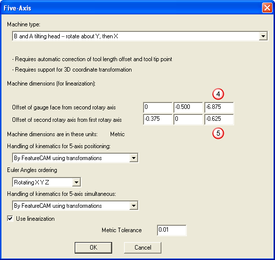
The five-axis dialog for a B and A tilting head machine is shown below. You enter machine dimensions so that FeatureCAM can correctly generate NC code based on the machine geometry. The fields are sets of X, Y, and Z values.
You need to understand three axes and a face to characterize the machine:
 first rotary axis centerline
 second rotary axis centerline
 spindle centerline (second axis)
 gauge face
These are labeled on the model of a B and A tilting head shown below:
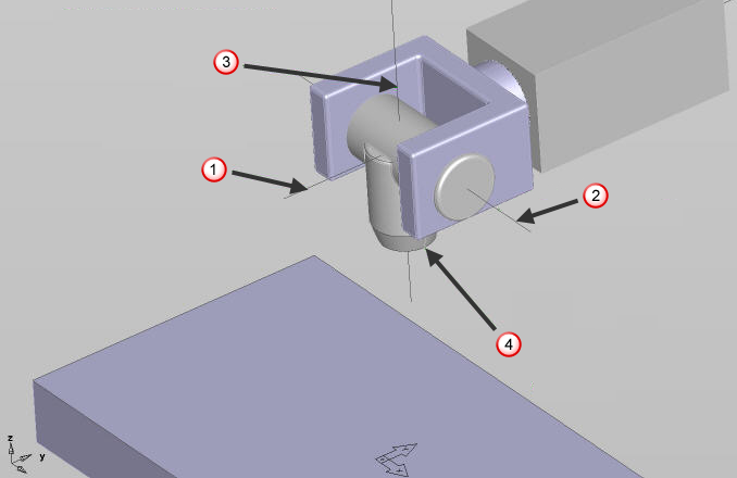
The first rotary axis for this configuration is the B axis and it is aligned with the Y axis.
The second rotary axis is the A axis and it is aligned with the X axis.
The first rotary axis carries the second rotary axis. In other words, when the first rotary axis is moved, the second rotary axis moves with it. If the second rotary axis (A) is moved, the first rotary axis (B) does not necessarily move.
The spindle centerline is the axis that passes through the center of the spindle. The gauge face is the gauge line or face of the spindle taper.
This is what distance each field should contain:
- The X coordinate of the Offset of gauge face from second rotary axis is always 0. There is no X distance possible between the gauge face and the second rotary axis centerline.
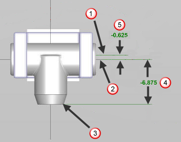
- The Y coordinate of the Offset of gauge face from second rotary axis is the distance from the second rotary axis centerline to the centerline of the spindle. See diagram below.
- The X coordinate of the Offset of second rotary axis from first rotary axis is the distance from the first rotary axis to the centerline of the spindle. See diagram below.
- The Y coordinate of the Offset of second rotary axis from first rotary axis is always 0. There is no y distance possible between the first rotary axis centerline and the spindle centerline.
|
|
|
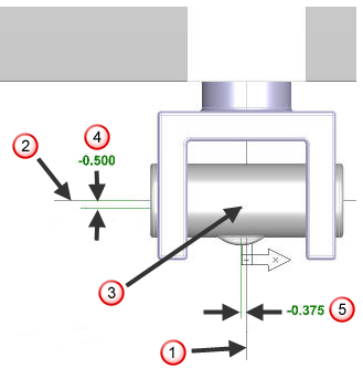
 X coordinate of the
Offset of second rotary axis from first rotary axis (see dialog below)
X coordinate of the
Offset of second rotary axis from first rotary axis (see dialog below)
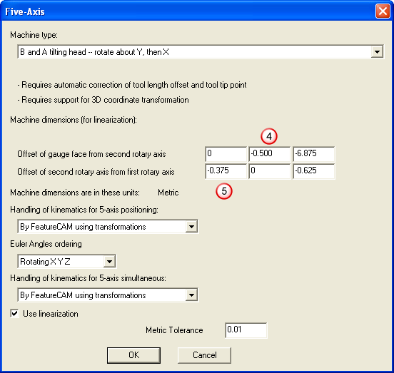
- The Z coordinate of the Offset of gauge face from second rotary axis is the distance from the second rotary axis centerline to the gauge face. See diagram below.
- The Z coordinate of the Offset of second rotary axis from first rotary axis is the distance in Z from the first rotary axis to the second rotary axis.
|
|
|