Specify the location of the feature:
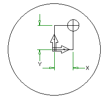
- XYZ — The feature is aligned so that its depth is parallel with the -Z direction of the Setup. You position it by specifying the X, Y, and Z coordinates in the plane of the Setup.
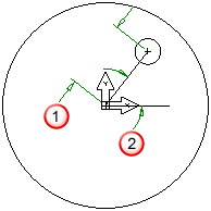
- Polar — The feature is aligned so that its depth is parallel with the -Z direction of the Setup. It is positioned by specifying a
Radius and
Angle.

 -
Radius
 -
Angle
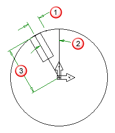
- Polar on the OD — The
Radius specifies the distance of the feature from the Z axis. The
Angle is the counter-clockwise angle, in degrees, from the X axis. The
Y shift distance is the distance the feature is translated from the radius in Y. The
Z coordinate is the distance the feature is translated in the Z direction. This option is available only for turn/mill documents.

 -
Y shift
 -
Angle
 -
Radius
- Radial about axis — For 4th-axis parts.

This point that you are specifying corresponds to the
 symbol in the diagrams.
To complete this page:
- Enter the location of a point in the
X,
Y, and
Z fields, or click
Pick location
 and select a point in the graphics window. Use
snap modes to select precise locations.
- If you are creating a Mill feature, enter an angle in the A field, that represents a counter-clockwise rotation around the feature location.
- Click Next.