You can use the Misc tab of the Milling Feature Properties dialog to edit the machining options of a Milling feature.
B-axis fixture location — This applies to B-axis turn/mill features.
Chamfer before finish — Enable this option to do the Chamfer operation before the Finish operation.
Deburr radius — Enter a radius to automatically round sharp outside corners of the feature by the specified radius. The feature shape does not change, but the toolpaths are modified to reflect the rounding.
Equal depth of cut — Enable this option to make each Z step equal depth.
Feed override % — Enter a scaling factor for the feed rates generated by the system. A value of less than 100 reduces the calculated feed rates. A value of more than 100 increases the rates.
Max. spindle RPM — Enter the maximum spindle speed (in RPM) that you want to use.
Min. corner radius — Enter a radius to automatically round the inside corners of a feature by the specified radius. The feature shape does not change, but the toolpaths are modified to reflect the rounding.
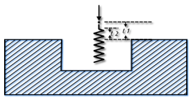
Plunge clearance — Enter the distance above the operation at which the tool feeds. You can override this value for the Finish operation on the Plunge tab.
This is marked as L1 in the diagram.

For deep hole drilling, the drill retracts to this distance between pecks. For milling features, the default is to use the same value for roughing and finishing. As a result, the tool feeds from the top of a feature to the floor before cutting. To make the tool feed down into the feature, set the Plunge clearance for an operation to a negative value, but ensure the value is above the floor of the feature.
To rapid to depth, you can use a negative Plunge clearance, or select Relative plunge.
Plunge feed override % — This gives the scaling value for the feed rate used during the initial plunge into the material for milling operations.
Retract to plunge clearance — Enable this option to retract to the Plunge clearance instead of the higher Z rapid plane after cutting.
Spindle RPM override % — Enter a scaling factor for the speed rates generated by the system. A value of less than 100 reduces the speed rate, and a value of greater than 100 increases it.
Spline tolerance — If a profile is defined as a spline, it is approximated with arcs and lines. Enter a tolerance value for the approximation. The smaller the tolerance, the smoother the profile.
Subfixture ID — This enables you to use a separate fixture offset for each feature, and corresponds to the <SUBFIXTURE> reserved word in XBUILD. For example, if the Fixture ID is 54 and you enter a Subfixture ID of 1, the output is 54.1.
For patterns, enter a Subfixture ID start value and a Subfixture ID increment value. For example, if the Fixture ID is 54 and you enter a Subfixture ID start of 1 and a Subfixture ID increment of 1, the output is 54.1, 54.2, 54.3, and so on.
Subfixture ID increment — See Subfixture ID.
Subfixture ID start — See Subfixture ID.
Tool % of arc radius — This controls the size of the tool that is automatically selected.
Z rapid plane — Enter the minimum safe distance in Z above your part.
Before performing a rapid move away from a feature, the tool retracts to the Z rapid plane setting for that feature. The rapid move to the next feature changes in Z height, that is, changes Z coordinates, if the next feature has a different Z rapid plane setting. So that when it arrives at the next feature it is at the Z rapid plane for that next feature.
This value is relative to the top of your stock in the current user coordinate system. Compare with Plunge clearance.