You can use the General page to edit the settings which affect all simulation types.
General
Tool Colors — Simulates the cuts of each tool with a different color.
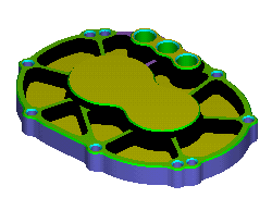
This lets you graphically view which portions of the part are cut with which tool. After you run a 3D simulation, you can toggle this setting without re-running the simulation. This image shows an example of tool colors.

For centerline simulation this option displays each tool in a different color during the simulation.
Show holder — Select this option to display the tool holder during centerline and 3D simulation.
Show spindle — Select this option to display the spindle during centerline and 3D solid simulation.
Simulation Speed — This controls the speed of the simulation. Position the slider on the scale between the far left for the minimum (slowest) speed and the far right for the maximum (fastest) speed. This slider controls the speed of 2D and 3D solid simulation.
Status
Use this section to specify what information you want to display on the Status bar during simulation:
Feed — Select this option to display the feed rate for the operation being simulated.
Speed — Select this option to display the spindle speed rate for the operation being simulated.
Time — Select this option to display the estimated current machining time.
Operation — Select this option to display the name of the operation currently being simulated.
Tool — Select this option to display the name of the tool performing the current operation.
Position — Select this option to show the X, Y, and Z positions of the tool on the screen. If you are using indexing, the angles you are rotated around the axes are also shown.