This topic describes two different methods to create a 3D representation from a 2D block asset: Extruding from a 2D block or associating a 3D model. Both procedures are performed using the 3D Representation menu option located in the Author panel on the Asset Builder tab. Once your 3D model is successfully associated to your block, it can be imported and positioned into the correct orientation.
To place a 3D component on a factory floor with the proper orientation, you must define a landing surface.
Accessing the 3D Representation Dialog
On the
Asset Builder tab, in the
Author panel, click
3D Representation
 to open the
3D Representation dialog box.
to open the
3D Representation dialog box.
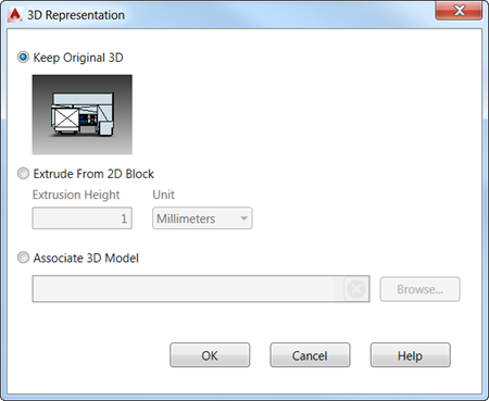
Extruding from a 2D Block
Associating a 3D Model
- This option lets you select an external 3D model to represent your block asset. Click the
Browse button to navigate to the
Choose a 3D Model dialog box and select the model you wish to associate. The following CAD formats are supported:
- STEP Files (.step, .stp)
- IGES Files (.igs, .iges)
- NX Files (.prt)
- SolidWorks Files (.prt, .sldprt, .asm, .sldasm)
- Pro/ENGINEER (.prt, .asm, .g, .neu)
- CATIA V5 (.CATPart, .CATProduct)
- JT Files (.jt)
- DWG 3D (.dwg)
- Inventor Files (.ipt, .iam)
- Navisworks Files (.nwd)
Note: When a Navisworks file is selected as the 3D representation, a 2D-only representation is used in Inventor.
- Once you have selected your model, a green checkmark appears in the 3D Assoc. column in the Block Browser dialog to confirm the successful association.
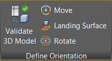
Validating and Orienting the 3D Representation
- On the
Asset Builder tab, in the
Define Orientation panel, click
Validate 3D Model
 .
.
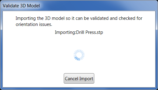
- The
Validate 3D Model dialog box opens and displays the following message as it imports the 3D model into your layout.
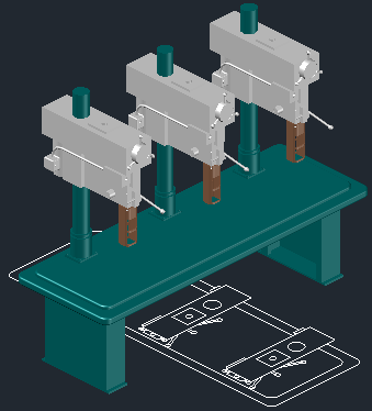
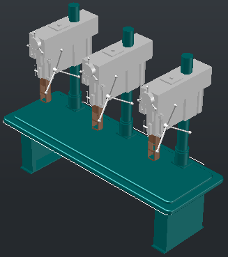
- The 3D model is placed over the 2D block in the graphics window. Observe from the image below that the orientation of the model does not match the orientation of the block.
- The
Define Orientation tab on the ribbon toolbar becomes active and offers
Move and
Rotate commands so that you can match the model orientation to the block.
Tip: Use osnaps to help you more precisely orient your model to the block.The model is shown correctly oriented with the block in the following image:
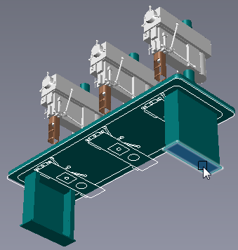
- Now that the model is correctly oriented, you must define its landing surface. The landing surface orients the component so that it is positioned against the floor. Click
Landing Surface from the
Define Orientation tab and use the
ViewCube to rotate the view to provide easy accessibility to the desire landing surface.
In the image below, the view has been rotated and the landing surface is selected.
- If necessary, you can make additional adjustments to the 2D block before publishing. On the
Asset Builder tab, in the
Block panel, click
Edit Block
 to open the AutoCAD
Block Authoring palette.
to open the AutoCAD
Block Authoring palette.
- When the steps listed above are complete, the asset can be published.