Properties help you manage and search for assets, create reports, and update bill of materials. When assigning or updating asset properties, keep in mind the following:
- If you update properties, those updates are not applied to assets already placed in your layout. To update placed assets, click Update Assets in the Factory Assets panel on the Factory tab.
- If an asset appears multiple times in a layout, but the properties differ, the asset appears as a single row in the bill of materials.
To assign properties to an asset:
- On the
Asset Builder tab, in the
Author panel, click
Asset Properties
 to open the Properties window.
- Enter
Summary information to help you search for this asset in the Asset Browser.
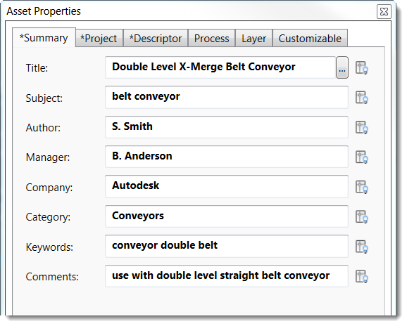
Note: The lightbulb icon that appears next to each field determines if the property value appears on the block in AutoCAD:
Click the icon to turn on the display. Leave the icon turned off to hide the display in AutoCAD.
These icons also appear for the Project and Descriptor fields, and for the Value field on the Customizable tab.
- The
Project tab includes information that is useful when preparing a bill of materials:
File Subtype File type; for example, dwf or ipt Part Number Part number of the asset. If you leave this blank, the file name is automatically assigned as the part number. Stock Number Stock number of the asset Description A brief description of the asset Revision Number File revision number Project Project name Designer Project or model designer Authority Signature authority Cost Center Cost center to apply to the asset Estimated Cost Cost of the asset used in the bill of materials and other cost calculations Create Date Today's date; click the calendar icon to select a different date. Vendor Manufacturer or supplier name if this is a third-party asset WEB Link Vendor link or other relevant Web site address - Click the Descriptor tab to add a description to the asset. The Descriptor field is set to display by default and pre-fills with the block name. The Extended Descriptor can include a more detailed description. The Extended Descriptor field also supports web site addresses, which appear as clickable links in the pop-up asset description.
- Enter
Process tab information to run simulations in Process Analysis.. If you are not using Process Analysis, skip to the Layer tab in the next step.
Process Object Check this box to designate this asset as a simulation object, and then select the object type: Buffer, Processor, or Source. The fields that appear vary based on your object type selection. Buffer Buffers temporarily store items produced by a processor.
Capacity: How many items the buffer can store.
Capacity Thresholds: Min (%) and Max (%) capacity thresholds trigger utilization alarms if the buffer is being under used, or is at or near capacity.
Output Routing: Routing method if this source is supplying material to one or more targets such as multiple production lines.
- Fixed Priority: Priority is given to the first target that was created.
- Shortest Queue: Select the target with the shortest queue.
- Longest Queue: Select the target with the longest queue.
- Round-Robin: Rotate targets in order, regardless of queue length.
- Random: Randomly select the target.
Select Ignore when unavailable to exclude a disabled target connected to an output route from output scheduling.
Operation Name: Name of the overall process model of which this processor is a part; for example engine assembly.
Operator There are no properties to predefine for an operator.
Processor Processors receive source materials or parts and perform operations on them.
MTBF: Mean time between failures for this processor and all of its operations; for example, 4400 hr indicates that, on average, this processor will run 4400 hours before failing.
MTTR: Mean time needed to repair this processor after a failure; for example, 60 min indicates that, on average it will take 60 minutes to repair.
Output Routing: Routing method if this source is supplying material to one or more targets such as multiple production lines. Select Ignore when unavailable to exclude a disabled target connected to an output route from output scheduling.
Utilization Alarms: The Min % and Max % trigger utilization alarms when the processor is producing slower or faster than the set threshold values.
Sequential Operations: Run the operations in the sequence shown.
Processor Operations: Add an operation to the list by selecting the
 button.
Name: Name of the overall process model of which this processor is a part; for example engine assembly.
Setup Time: Time required to set up the processor to perform this operation.
Processing Time: Number of items processed in the selected unit of time.
Minimum Quantity: The minimum amount of items to be processed by an operation before the processor switches to another operation.
Product Target Quantity: How many end products you would like to produce during a simulation.
Production Rate Unit: Determines whether the rate of production is producing a rate per second, minute, hour, or day.
Source Sources are raw materials or parts entering a factory workflow.
Quantity: Number of items available from this source. Select Infinite if there is an unlimited supply.
Output Rate: Number of items the source supplies in the selected unit of time. If the rate can vary, enter the acceptable range as a percentage of the output.
Output Routing: Routing method if this source is supplying material to one or more targets such as multiple production lines. Select Ignore when unavailable to exclude a disabled target connected to an output route from output scheduling.
- The
Layer tab lets you select an existing layer or define a new layer in which to place the asset. Automatic layering is useful if you want to control the visibility of this asset in complex designs.
Select Specify Layer for Asset to associate a layer with this asset. If you do not select this checkbox, the asset will be placed in the current DWG layer in AutoCAD or current layout layer in Inventor. To create a new layer, type a name in the text box and select a color to represent the layer. To select an existing layer, choose one from the list that appears. The list shown is pulled from the file designated under the Asset Builder option in the AutoCAD Options Factory Assets tab. If no file is designated in the settings, the layer list is blank. See Setting Factory Asset Defaults for more details.
Note: You must select the Enable Automatic Layering check box on the Factory Assets Options tab to activate this feature. See Setting Factory Asset Defaults for details. - The
Customizable tab lets you add custom properties to help you track asset data. Information entered here appears in the Factory Properties browser organized by category:
Click Add to add the property to the list. The Delete button deletes the selected property from the properties list.
Name Enter a new property name or select an existing customizable property for editing. Type Select a data type. Value Enter a value that conforms to the selected data type. Category Enter a new category name or select an existing one.
After you define these properties and publish the asset, you can place it in your AutoCAD and Inventor layouts.