- Inventor HSM Express - 2D Milling functions supported by Inventor LT and Inventor.
- Inventor HSM Professional - 2D and 3D Milling, 3+2 Milling plus Turning functions supported by Inventor LT and Inventor.
- Inventor HSM Ultimate - 2D, 3D, 3+2 Milling, Simultaneous Multi-Axis Milling plus Turning functions supported by Inventor LT and Inventor.
The command ribbons and the commands they offer for the three different versions of Inventor HSM appear below:
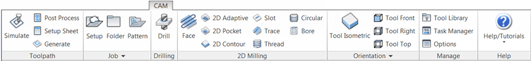
The Inventor HSM Express command ribbon
The Inventor HSM command ribbon

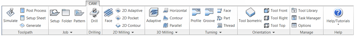
The Inventor HSM Professional command ribbon
Once a part or assembly file is loaded and a strategy selected from the CAM ribbon, the CAM Browser becomes active replacing the familiar Inventor Model Browser. The CAM Browser lets you view and modify all machining-related data in the current part or assembly.
To create your first machining operation, simply select any of the toolpath strategies from the CAM toolbar. The type of toolpath required naturally depends on the geometry of your part. For a description of the individual machining strategies, please refer to the Inventor HSM Help topics: About 2D Machining Strategies and About 3D Machining Strategies.
The following example illustrates a 2D Pocket strategy which is used to remove the interior cavity of a part .
Normally a machining operation, like pocketing, is started by creating a Setup. A setup defines a number of general properties for a set of machining operations - including the Work Coordinate System (WCS), the stock geometry, fixtures, and the machining surfaces. If you do not create a setup manually before adding your first operation, a setup with default parameters is created for you automatically. For more information about creating a setup, see the Help topic: Setup Reference.
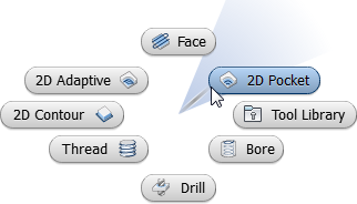
You select the first operation you wish to perform on the workpiece by clicking the appropriate icon from the command ribbon. In this example, you would click
CAM tab  2D Milling panel
2D Pocket
2D Milling panel
2D Pocket
 .
.
The
Operation dialog box then replaces the
CAM Browser at the left side of the graphics window, and prominently displays in its title bar the strategy name you selected. Just to the right of the strategy name is the operation number. Since this is the first 2D pocket operation for the part, the name displays as
2D Pocket1. The next 2D pocket operation will display as
2D Pocket2, and so on. This naming convention applies to all setup and machining strategies in
Inventor HSM.
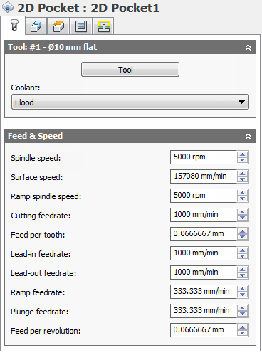
The Operation dialog box for the 2D Pocket strategy. Note that the Tool tab is active by default..
Click the Tool button to open the Tool Library. Select an existing tool from a tool library by expanding the tree, selecting a tool, and clicking the OK button. Alternatively, you can create a new tool by clicking the New Mill Tool button, editing the parameters, and then clicking the Select button.
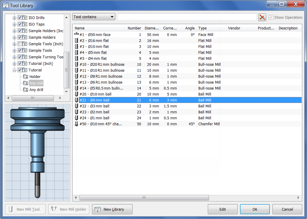
A Ø6 mm ball mill is selected from the Tool Library
Once you have selected your tool, click the Geometry tab and select the geometry to be machined. For the 2D Pocket strategy, you need to select one or more closed contours. You can select directly from the model by clicking on edges, faces, surfaces, etc., but you can also use any 2D sketch directly.
When selecting 2D geometry, the contours are projected onto a plane parallel to the tool orientation. If the projection looks incorrect, you can change the tool orientation by clicking on the Tool Orientation section on the Geometry tab and selecting a different plane.
Having successfully generated a toolpath, you can see a preview of the toolpath generated on top of the model simply by selecting the corresponding operation in the CAM Browser.

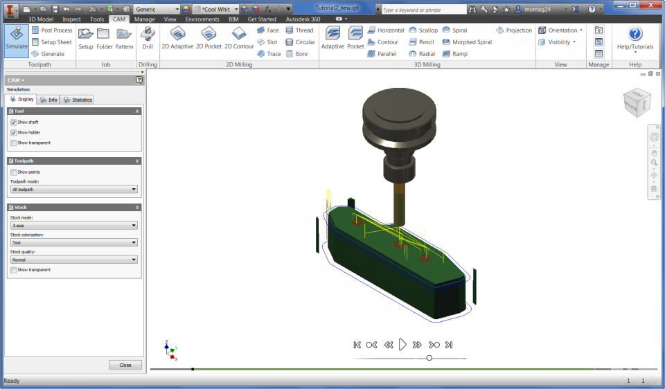
Toolpath Simulation
To simulate the toolpath, select one or more operations from the
CAM Browser (multiple operations can be selected by pressing and holding the
Ctrl key while clicking with the mouse), and then click
CAM tab
Toolpath panel
Simulate
 on the CAM ribbon.

Stock Simulation
To invoke the solid simulation, enable the Stock check box in the Simulation dialog.
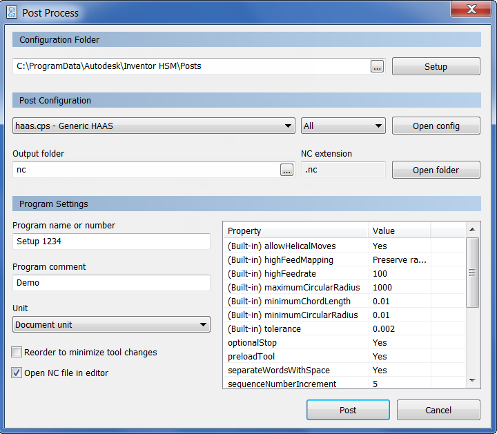
Post Processing
Inventor HSM ships with a number of customizable post processors that can be invoked by selecting one or more operations from the
CAM Browser, and clicking
CAM tab
Toolpath panel
Post Process
 on the CAM ribbon.
General Information
Multi-selection
Multi-selection of items in the CAM Browser is supported using the Shift and Ctrl keys.
- To select consecutive items, click the first item, press and hold the Shift key, and then click the last item.
- To select non-consecutive items, press and hold the Ctrl key, and then click each item.
Log Messages
If an operation in the CAM Browser is overlaid with an orange checkmark, it indicates that the operation could not be generated successfully. To see a description of the problem or error, right-click the operation and select Show Log from the pop-up context menu. The log is displayed in a dialog box and explains what went wrong.
Associativity and Regeneration
When you define operations in Inventor HSM, all relations to the model are associative. That means that if you change your model, you will not have to redefine any parameters and selections again - they will persist across model changes and rebuilds. You will, however, have to regenerate your operation whenever a part of the model is modified on which the operation depends.
When a modification of the model triggers invalidation of a toolpath, the regeneration symbol (i.e. a red cross) is overlaid on the corresponding operation and toolpath nodes in the CAM Browser. If you try to use an invalidated toolpath, you are notified that it requires regeneration.
Toolpath panel
Generate
 from the CAM ribbon regenerates all operations that require regeneration.
While regenerating toolpaths, the
Inventor HSM
Task Manager dialog is shown. This shows the progress of any ongoing toolpath calculation, but can be hidden by clicking the
Hide button so that you can continue working while the regeneration completes. Normally, 2D toolpaths generate in a matter of seconds, but some of the 3D strategies can take a considerable time to calculate, depending on the geometry and tolerances. If you have hidden the
Task Manager dialog, you can restore its visibility by clicking
CAM tab
Manage panel
Task Manager
 .
.
Use Assemblies
The machining operations created in a part or assembly are stored with the Inventor file itself - including the generated toolpath. This Inventor HSM data remains within the file even if it is edited on a system that does not have the Inventor HSM add-in installed. To remove the Inventor HSM-specific data from a part or assembly file, simply delete all operations from the CAM Browser and save the file.
You will notice that the toolpath data of machining operations can cause the size of your files to grow considerably. If you wish to send the file by e-mail or similar, you may want to clear the not required toolpath data from the file before sending it. Simply right-click the operation(s) and choose Clear Toolpath before saving the document. The toolpaths can then be regenerated by the receiver from the file containing only the parameters.
If you do not wish to add Inventor HSM-specific data to your design model, you can create a separate assembly for the Inventor HSM data and insert the parts you want to machine as assembly components, which leaves the component part files unaffected by the Inventor HSM add-in - the machining data and toolpaths will reside only in the assembly file along with any extra reference geometry (e.g. coordinate systems) you may want to define for your operations.
Metric or Imperial Units
Inventor HSM supports input in either inches or millimeters for parameters. If metric units are selected for the Inventor document system units, then the parameters units will be set to millimeters. This also applies to inch units. The tool parameters are specified in the units of the tool geometry.
3+2 Machining (HSM Professional & up)
By default, new operations are created using the WCS (Work Coordinate System) of the current setup. If the default WCS is incorrect, you can change it in the Setup dialog box. To change the tool orientation of a single operation only, open the Geometry tab for the operation, and change the settings in the Tool Orientation section.
A tool orientation can be specified as one of the following:
- Use WCS
- Use Point & Plane
- Use Coordinate System
For most common cases, using Use Point/Plane is the easiest way to define the tool orientation, since that allows you to select any point or vertex as the origin of the tool, and any face, edge, or plane as the orientation.
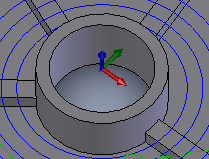
Whenever an operation is selected, a small coordinate system is drawn on top of the model to indicate the tool orientation. The coordinate system is placed at the origin of the tool orientation. The red, green, and blue arrows correspond to the X, Y, and Z-axes respectively. Machining is always done from positive Z towards negative Z (e.g. opposite of the blue arrow).
Boundaries
You can restrict every machining operation to one or more areas by specifying boundaries. The default boundary used is the bounding box of the part geometry being machined. You can select silhouette curves of the part geometry or a selection, for example a chain of edges, to confine the area of machining. Boundaries can be nested, but a boundary should not intersect itself or other boundaries.
Rest Roughing
The most efficient roughing is achieved by following the work of a large tool with a smaller tool in the areas that have not yet been cleared by the previous operation.
To achieve this, Inventor HSM uses a stock model of the remaining material to avoid air-cutting. The stock model can be generated from a previous operation or supplied by you. In some cases, for example, very large work pieces may require several rest roughing stages; with each stage using a smaller tool than the previous operations. There is no restriction on the number of rest roughing stages.
Rest Material Machining
For the clearing of rest material with a smaller tool, any Inventor HSM strategy can be used; whichever is most suitable. The area to be machined is defined by the tool and the machining strategy used in the previous operation.