Support for Associative DWG Underlay in Drawings
These enhancements to associative DWG underlay streamline data re-use, translation, management, and the design change update processes.
You can now include DWG underlays in drawings and do the following:
- Add text and dimensions to annotate the DWG underlay geometry.
- Easily manage layer styles and line types. The AutoCAD layer styles and line types are imported into the drawing file. Use the Styles Editor to manage the layers and line types as needed.
Changes made to the DWG underlay geometry in the corresponding Inventor file associatively update in the drawing file. To associatively update changes made in the AutoCAD file in the drawing file, you must first update the DWG underlay in the part file.
For more information see, To Work with Associative DWG Underlays in Drawings.
New Crop Workflow for DWG Underlays in Parts
You can now:
- Crop the DWG underlay to improve performance and remove unwanted data in part files. Cropping allows you to focus on the relevant design area when you are working with a large DWG file.
Underlay geometry cropped in a part file displays as cropped geometry in a drawing view of the part file.
- Add constraints and joints to cropped underlays in an assembly file.
For more information see, To Work with Associative DWG in a Part and Assembly File.
Support for Associative Placement
The location of a DWG underlay now associatively updates when the location of the DWG underlay's plane and/or insertion point changes. For example, if you place a DWG underlay on the corner of a model, and then change the location of the corner of the model, the location of the DWG underlay updates associatively. The changes you make with the Translate command are now also associative.
- 2d Sketch point, start/center/end point of 2d sketch curves
- Start/center/end point of edges
- Center point of face
- Work point
- Vertex
Support for changing and re-establishing the associative plane and origin point
- Use the new
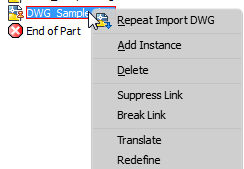
Redefine browser context menu option to:
- Move the DWG underlay to a different associative plane and origin point.
- Reconnect the DWG underlay's plane/point of associativity if the dependent plane and origin point are deleted.
- Re-establish associativity with legacy files: The associativity that exists in a DWG Underlay Inventor 2016 part or assembly file is not maintained when you open the file in Inventor 2017. Use the Redefine command to re-establish the associativity.
For more information see, To Work with Associative DWG in a Part and Assembly File.
Reinsert a DWG with Ease
You can now easily reinsert the same DWG file into the part file: Right-click the DWG node in the browser, and select the new context menu option, Add Instance.
For more information see, To Work with Associative DWG in a Part and Assembly File.