Enhancement to Circular Pattern Allowing Identical Occurrences
Select Fixed to preserve the orientation of the body or source feature set. You can also redefine the base point for your body or feature set. The default uses the intersected profile center for the base point.
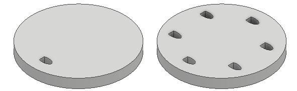
For more information, see To Arrange Part Features in Patterns.
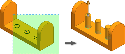
Sketch Driven Pattern
The Sketch Driven Pattern command is introduced. You can now pattern features or bodies on sketch points defined in a 2D or 3D sketch. Optionally, you can redefine the Base Point or pick Faces to orient the pattern.
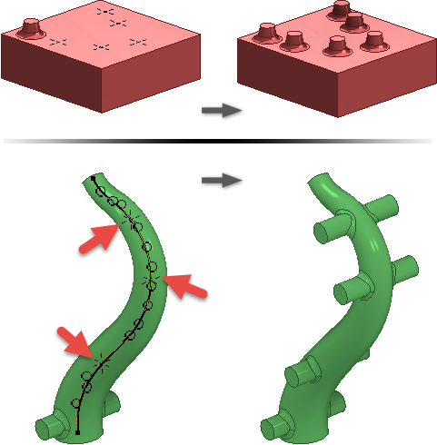
For more information, see To Arrange Part Features in Patterns.
Boundary Patch
The Guide Rails option is added to the Boundary Patch command. You can now select curves and points to shape the patch.
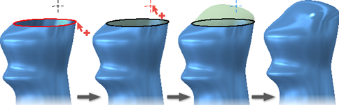
For more information, see To Create Patch, Stitch, or Ruled Surfaces.
Ruled Surface
- The Angle option is added to all ruled surface types.
- The Sweep surface type is renamed Vector and now supports both edge and sketch selection.
- Alternate All Faces and Automatic Edge Chain is added to the Vector surface type.
For more information, see To Create Patch, Stitch, or Ruled Surfaces.
Window Cross Select Multiple Closed Profiles Within the Extrude Command
You can now use a window to select multiple closed profiles when you use the Extrude command. Previously, you had to select closed profiles one at a time.
For more information, see To Create Extruded Features.
View the Parent/Child Relationship Feature from Within a Part
In the Part environment, you can now easily access the parent/child-feature relationships from a part through the model browser or graphics window. This new interactive dialog box allows you to view feature dependencies from directly within your part. In the Relationships dialog box, select the
 icon to switch to a Selected view. Select the
 icon to access the Edit Feature dialog box.
- Sketches
- Shared sketches
- Axes
- Planes
- Points
To access the Relationships dialog box and viewable feature dependencies:
- Model browser: Right click the feature node in the model browser to display the context menu and select Relationships...
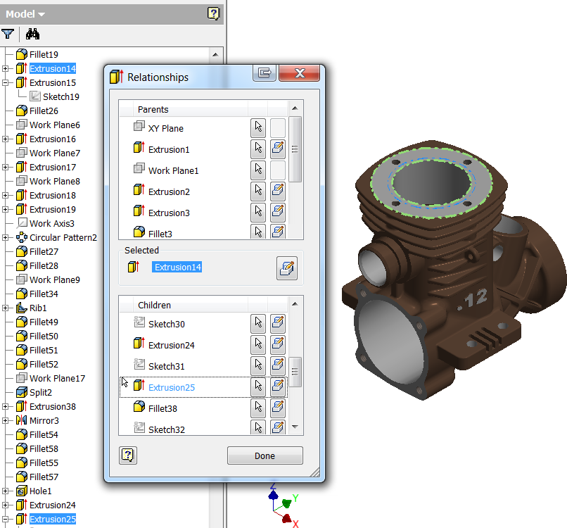
- Graphics window: Set the selection filter to Select Features, select a feature in the display, right-click, and select Relationships...
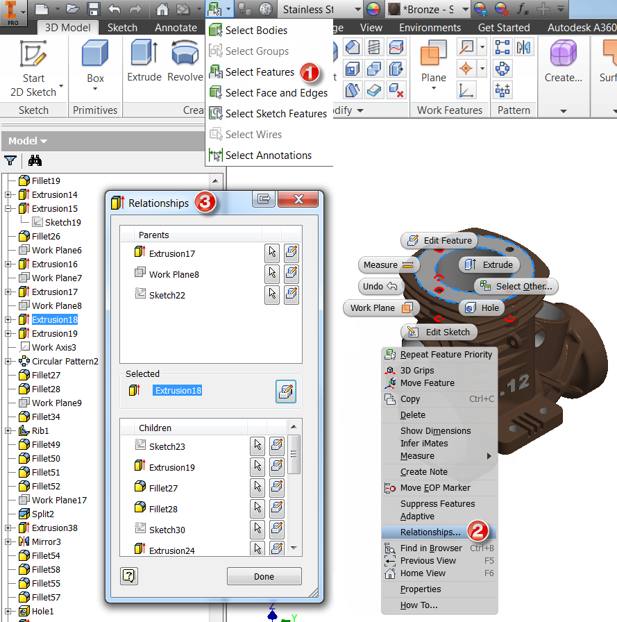
For more information, see To Find Relationships in Part.
Part File Template
View representations in the part file template are enhanced to make it simple to document your design.
- Master (locked)
- Isometric (default)
- Front
- Top
- Right