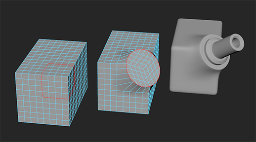
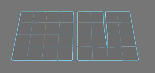
- Found in the Modeling menu set.
Components
- Add Divisions
-
Splits selected polygon components (edges or faces) into smaller components. Add Divisions is useful when you need to add detail to an existing polygon mesh in either a global or localized manner. Polygon faces can be divided into three-sided (triangles) or four-sided (quadrangles) faces. Edges can be subdivided so that the number of sides on a face is increased.
Select to set the Add Divisions Options.
Note: The contents of the Add Divisions Options window changes depending on what component selection mode you are currently in. - Bevel
-
Creates beveled polygons along the currently selected edges or faces. See Bevel command and Bevel polygon edges and faces.
Select to set the Bevel Options.
- Bridge
-
Constructs a bridging polygon mesh (additional faces) between selected pairs of border edges on an existing polygon mesh. The resulting bridging polygon mesh is combined with the original polygon mesh and the edges are merged. See Bridge Command and Bridge between border edges.
Select to set the Bridge Options.
- Circularize
-
Reorganizes the current selection of components (vertices, edges, or faces) into a perfect geometric circle. See Circularize components.


Select to set the Circularize Options.
- Collapse
- Collapses edges on a component by component basis and then merges the associated vertices for each collapsed edge separately. Collapse also works on faces, but produces results that are more predictable when using edges. If you wish to collapse and merge a selection of faces you should first select .
- Connect
- When vertices and/or edges are selected,
Connect connects them via edges. Vertices are connected directly to connecting edges, while edges are connected at their midpoint.
Select to set the Connect Components Options.
- Detach
-
When vertices are selected, Detach separates any selected vertex that is shared by multiple faces into multiple vertices depending on the number of faces the vertex shares. The edges of the faces associated with the vertex also become unshared as a result. When faces are selected, Detach separates the face selection along its perimeter edges. When edges are selected, Detach separates the selected edges into two overlapping edges. If you perform a Detach operation over a path of edges, the vertices along that path are also separated along that path. The vertices at the ends of each selection remain attached to both of the new edges or edge paths. If both vertices and edges are selected, Detach defaults to the same behavior as when only vertices are selected.
 Note: Detach ignores any vertices that are not shared.
 - Extrude
-
Pulls new polygons out from existing faces, edges, or vertices, with options to transform and reshape the new polygons as they are pulled out from the selected originals. See Extrude command.
Select to set the Extrude Options.
Note: The Keep Faces Together setting can be turned on and off when using Extrude by Ctrl +Shift + right-clicking on the object whenever the Show Manipulator Tool is displayed. - Merge
- Merges selected edges and vertices that are within a specified threshold distance of each other. For example, two selected edges will be merged into one shared edge.
Select to set the Merge Components Options.
- Merge to Center
-
Merges the selected vertices so they become shared, and any associated faces and edges are also merged. The resulting shared vertex is positioned at the center of the original selection.
Note: Merge to Center merges to a central point based on the center of the selection. If you want to collapse edges on a component by component basis, select the edges, then select , or choose from the marking menu. (To open the marking menu, Shift + right-click an edge.) - Transform
-
Transform lets you move, rotate, or scale polygon components (edges, vertices, faces, and UVs) relative to the normal while creating a history node.
Select to set the Transform Components Options.
- Flip
-
Swaps the position of selected components with their mirrored counterparts across an axis of symmetry. See Symmetrize asymmetrical components
- Symmetrize
-
Moves components to the mirrored position of the corresponding components across an axis of symmetry. See Symmetrize asymmetrical components.
Vertex
- Average Vertices
-
Smooths the polygon mesh by moving the positions of the vertices. Unlike Mesh > Smooth, the Average command does not increase the number of polygons in the mesh.
Select to set the Average Vertices Options.
- Chamfer Vertices
-
Replaces a vertex with a flat polygon face.
Select to set the Chamfer Vertices Options.
- Reorder Vertices
-
Allows you to reorder the vertex IDs on a polygon object. For more information, see Modify or transfer vertex orders.
Edge
- Delete Edge/Vertex
- Deletes blatant edges or vertices from the polygon mesh depending on what components are selected. When vertices are selected, it removes any shared vertices that are selected on the mesh. Shared edges associated with the selected vertices are also removed as a result. The faces surrounding the deleted vertices and edges are replaced with a single n-sided polygon created from the vertices surrounding the deleted vertex. When edges are selected, it removes any shared edges that are selected on the mesh as well as any shared vertices that are associated with the deleted edges.
Delete Components does not delete border edges on a polygonal mesh.
Tip: You can also press Ctrl + Delete or Ctrl + Backspace to quickly delete components.
- Edit Edge Flow
-
Lets you change existing edges to respect curvature continuity.
Select to set the Edit Edge Flow Options.
- Flip Triangle Edge
- Switches the polygon edge dividing two triangle polygons so it connects between their opposite corners.
Note: You can access Flip/Spin Edge from the marking menu by Shift + right-clicking when the polygon is in Edge mode.
- Spin Edge Backward
-
Spins the selected edges opposite to their winding direction, changing their connectivity 1 vertex at a time.
Note: You can access Flip/Spin Edge from the marking menu by Shift + right-clicking when the polygon is in Edge mode. - Spin Edge Forward
-
Spins the selected edges in their winding direction, changing their connectivity 1 vertex at a time. Edges must be attached to only 2 faces in order to be spun.
If you spin an edge multiple times, Maya edits the offset attribute of the existing history node. Spinning an edge does not affect the vertex IDs or edge IDs, however as you spin an edge, the adjacent faces rotate along with it.
Face
- Assign Invisible Faces
- Toggles selected faces as invisible. Faces assigned as invisible do not appear in the scene. However, these faces still exist and can still be manipulated.
Select to set the Assign Invisible Faces Options.
- Duplicate
- Creates a new separate copy of any selected faces. The duplicated faces become part of the original mesh which otherwise remains unaffected.
Select to set the Duplicate Options.
- Extract
- Detaches the selected faces from the associated mesh. The extracted faces become a separate shell within the existing mesh. If you select the mesh in object mode both the mesh and any extracted faces get selected.
Select to set the Extract Options.
- Poke
- Splits the selected faces to let you push or pull the center of the original polygon. For example, a four-sided polygon (quad) is split into 4 three-sided polygons with one shared vertex in the middle. A manipulator appears after the
Poke operation to let you further transform the vertex.
Select to set the Poke Options.
- Wedge
- Pulls an arc of new polygons from existing faces.
Select to set the Wedge Options.
Curve
- Project Curve on Mesh
- Projects a curve onto a polygon surface.
Select to set the Project Curve on Mesh Options.
- Split Mesh with Projected Curve
- Splits or splits and detaches edges on a polygon surface.
Select to set the Split Mesh with Projected Curve Options.
