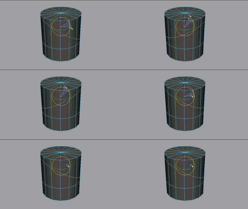
 You can activate the
Edge
Transform Constraint when in component mode by Ctrl + Shift + dragging the
Move,
Rotate, or
Scale Tool manipulators (or Ctrl + Shift + middle-dragging anywhere on the screen when they're active).
Alternatively, you can activate it via the Transform Constraint option in their Tool Settings.
To slide polygon components along their edges
- Select the component(s) you want to slide on the polygon mesh.
You can Shift-select or double-click vertices to select an entire edge loops. See Select an edge loop.
- Double-click a transform tool in the Toolbox.
- In the
Tool Settings that appear, select
Edge from the
Transform Constraint drop-down menu.
Note: You can also transform components along a polygon surface. For more information, see Move polygon components along a surface.
- Do one of the following:
- Use the Move tool manipulator to slide components along connected edges.

- Use the Rotate tool manipulator to slide a component loop.

- Use the Scale tool manipulator to slide a component loop.

- Use the Move tool manipulator to slide components along connected edges.
- In the
Tool Settings or
Modeling Toolkit window, select
Off from the
Transform Constraint drop-down menu to transform components without a constraint.
Tip: Middle-click the transform constraint button
 in the
Modeling toolkit to toggle the last selection.
Sliding polygon edges using the Slide Edge Tool
When working with edges specifically, you can also use the Slide Edge Tool to move them along their adjacent edges. This affords you some extra Snapping and Relative versus Absolute options.
To slide polygon edges using the Slide Edge Tool
- Select the edges you want to slide on the polygonal mesh.
You can Shift-select edges or double-click to select an entire edge loop (see Select an edge loop). You can also select edges using Symmetry.
- Select .
- Middle-drag to slide the selected edges.
The vertices associated with the selected edges move along their shared perpendicular edges.
Tip: Press the Shift key to move the edges/edge loop along each vertex normal.Tip: If Symmetry is currently enabled then corresponding edges across the line of symmetry will move in mirrored fashion.