Viewport 2.0 rendering events Profiler examples
Profiler results will naturally vary depending on the scene being examined. The first set of examples examine the basics of UI and non-UI drawing, as well as the list building update events, and the overall sequencing for a scene render.
The next set of examples discuss the differences in sequencing when a render override or plug-in renderer is active, as well as examine rendering into other viewports such as the UV Editor.
Empty scene
The simplest possible case is an empty scene with no UI. A snapshot of the higher level events is shown below. Event granularity increases from the bottom of the graph to the top.

- Bottom row:
- Vp2SceneRender: Event that encompasses the processing for a scene render
- Middle row:
- Vp2UpdateScene: Event that encompasses the main update and rendering events
- Top row (left to right)
- Vp2UpdateVisiblityTask: Is relatively minor as there is nothing to draw
- Vp2UpdateUI: UI drawable update
- Vp2BuildRenderLists: Relatively small percentage of time spent, as there is no non-UI to process
- Vp2Draw3dBeautyPass: Makes up the majority of the time spent for drawing
UI drawing (grid)
When the grid is enabled, the profile shows some of the lower level list drawing. At this level, the colorPass event dominates, with rendering of the beauty pass UI taking up most of the time.
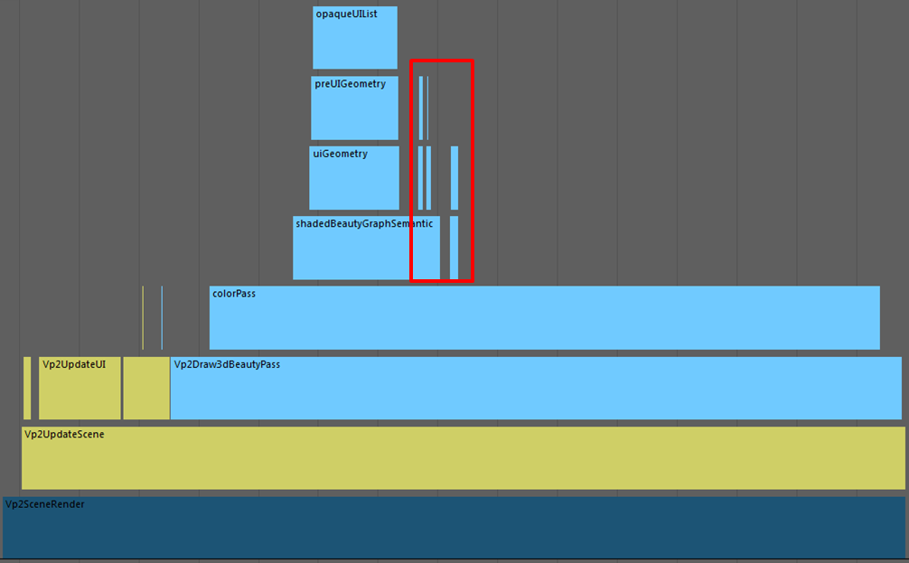
The rows above the colorPass event show a finer granularity breakdown that includes the pass semantic named events for drawing opaque UI list elements (opaqueUIList), which includes the grid. The uiGeometry semantic denotes that UI is being rendered. The preUIGeometry semantic indicates that it occurs before the beauty pass. The smaller events marked by the red box are postUIGeometry, which indicates processing of the UI after the beauty pass.
To examine changes in the UI display, enable all HUD elements:

This change results in an increase in the percentage of processing time used for the UI update (Vp2UpdateUI) and a decrease for the Vp2BuildRenderLists.

Opaque object drawing (spheres)
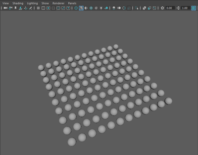
Conversely, adding a number of non-UI objects, such as a set of meshes as illustrated below, results in the render list building event becoming more pre-dominant. An additional event (opaqueGeometry semantic) also appears, which marks the drawing of the opaque geometry list (sphere).
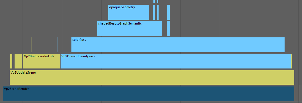
This sequence of events can be seen as a subset of events that occur when using a render override.
Render override examples
As with the previous set of examples (where an override was not used), this section will start with a simple example, and add complexity for subsequent examples.
The following render overrides are available as example plug-ins in the Maya Developer Kit.
viewOverrideSimple
In this example, the “top” level event is labelled Vp2OverrideRender, which indicates that a render override is being used.

The graph increases in granularity from the bottom towards the top. The Vp2ExecuteRenderOverride shows the internal execution time while the Vp2*Operation events are performed. This example uses a scene, a HUD (outlined by the red box) and a present operation (Vp2SceneOperation, Vp2HUDOperation, and Vp2PresentOperation, respectively).
As a color pass is required, an internal scene render event occurs (Vp2SceneRender). The Vp2DrawOperation event label indicates operation rendering, but as the yellow box illustrates, the sequence of events that occur in this graph are nearly identical to those shown in the opaque internal rendering example above.
viewImageBlitOverride
This example shows a different configuration wherein an external renderer is assumed to have produced an image, and what is required is an image blit, followed by rendering the UI elements in Maya.
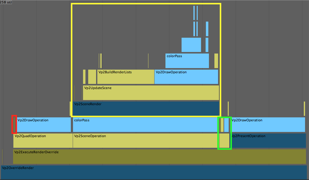
For the update phase, the event outlined in red is the per operation update time (Vp2UpdateOverrideOperation).
The basic operations are a quad, scene, HUD (outlined by the green box), and present operation (Vp2QuadOperation, Vp2SceneOperation, Vp2HUDOperation, and Vp2PresentOperation).
The scene operation (outlined by the yellow box) has the same basic event sequence as discussed in the previous two examples.
viewRenderOverride
The final render override example examines a mix of quad, scene, user, HUD and presentation operations. The sample scene profiled is as follows:
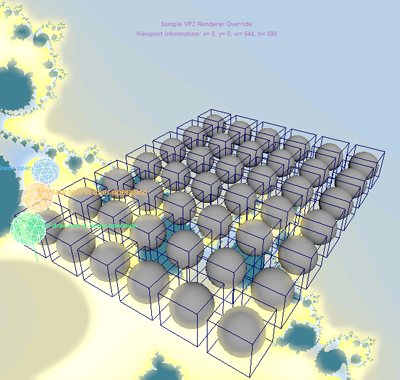
The basic rendering operation sequence is as follows:
- Draw a procedurally generated background; in this case, Mandelbrot.
- Draw the non-UI parts of the scene.
- Perform a 2d color intensity threshold function on the rendered image to produce a new image.
- Blur the thresholded image.
- Combine the thresholded image with the scene rendered in step 2. This results in a "glow".
- Draw the UI parts of the scene.
- Perform a custom user pass for additional UI.
- Draw the 2D HUD.
- Present the final output.
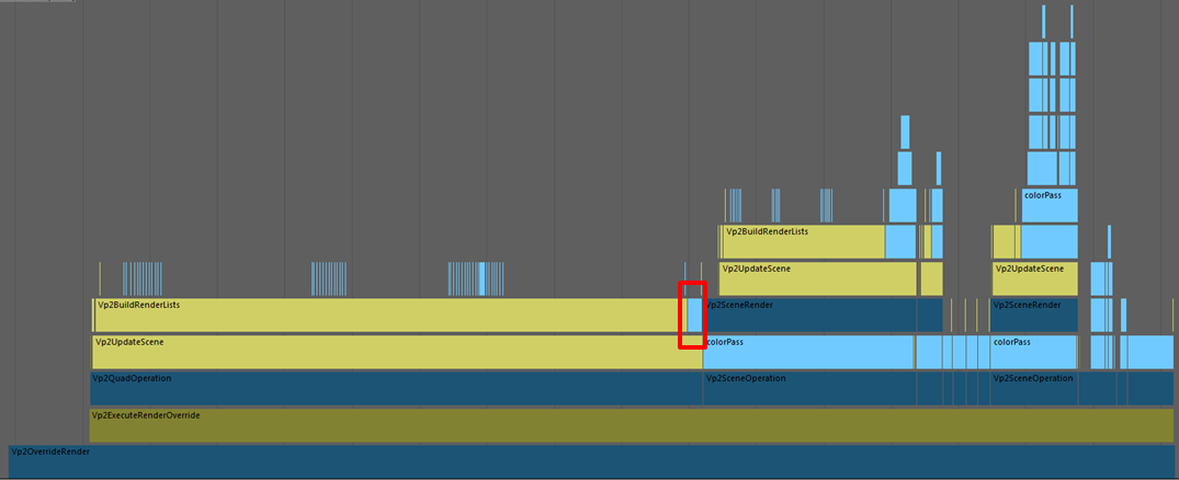
In the following graph, the relative event times are shown for each operation, and the first quad operation is more expensive than the others. For a simple scene with a few spheres, a fair percentage of the time is spent preparing render item lists as opposed to drawing the procedural Mandelbrot pattern (Vp2DrawOperation outlined in red).
The following graph shows the events that occur after the background render:

The events outlined in yellow represent an opaque and a transparent scene draw operation. Both have disabled drawing of any UI elements. Note that the time spent for the transparent draw is much smaller than for the opaque due to processing that has already been done for the opaque draw, as well as the fact that there are fewer transparent items.
The events outlined in red correspond to 4 quad render operations used for thresholding, a vertical blur, a horizontal blur and compositing with the original image.
The final scene operation events outlined in green represent the drawing of UI elements. A longer event processing time occurs for UI elements (Vp2UpdateUI), such as the wireframe and bounding box drawing, as this event also includes custom UI drawables added in the plug-in.
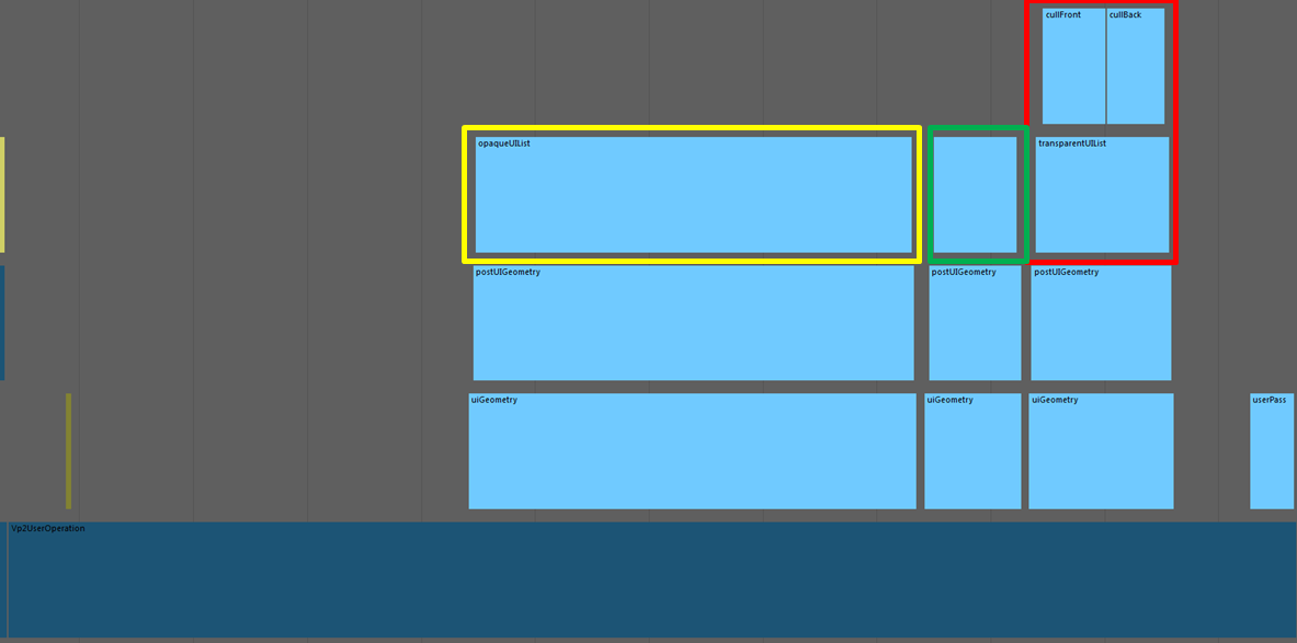
The user operation adds more UI drawables. Expanding the events in the Profiler demonstrates that opaque and transparent lists are handled differently, as a “default” front/back culling 2-pass drawing occurs for transparent objects. The opaque list handling is outlined in yellow and the transparency list handling in red. The green box outlines the processing for bitmap drawing. The user operation code itself is a non-operation.
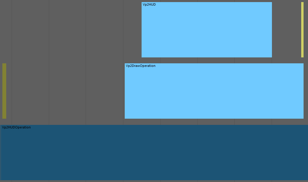
Lastly, the separated HUD operation is very straight-forward and ends up rendering all items on the HUD list (Vp2HUD). The dark yellow colored event shows operation update processing.
Non-3d render graphs
Overlay drawing
The following graph demonstrates the set of events found when profiling the 2d marquee select tool. Overlay drawing is indicated by the “Vp2DrawOverlay” label. The list drawn is the “Vp22d Overlay UI” list. There is no 3d rendering involved.

Plug-in Renderer for Material Viewer
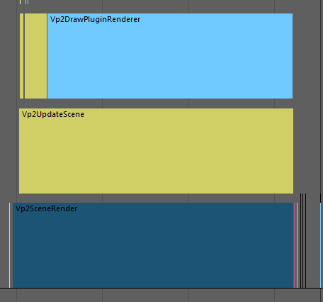
The following graph demonstrates the profiling results for a simple update of the plug-in renderer used in the Material Viewer of the Hypershade. The majority of time is spent in displaying the rendered image (Vp2DrawPluginRenderer).
UV Editor
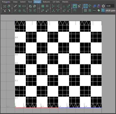
The UV Editor, for the most part, consists of drawing UI. This includes the opaque draw for the background image as well as the wireframe, grid and other decorations. The following sample scene with a checker on a Lambert shader is profiled.
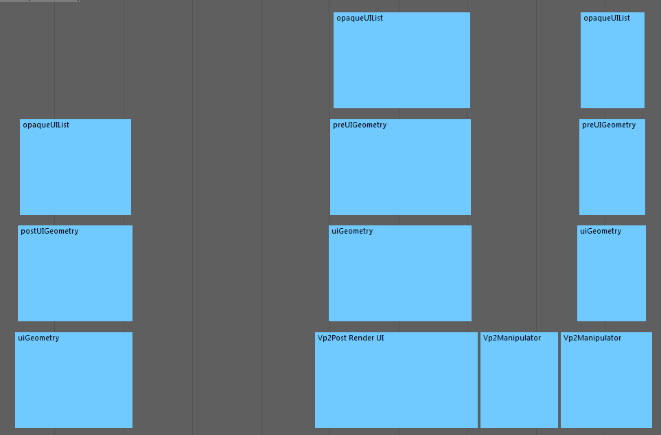
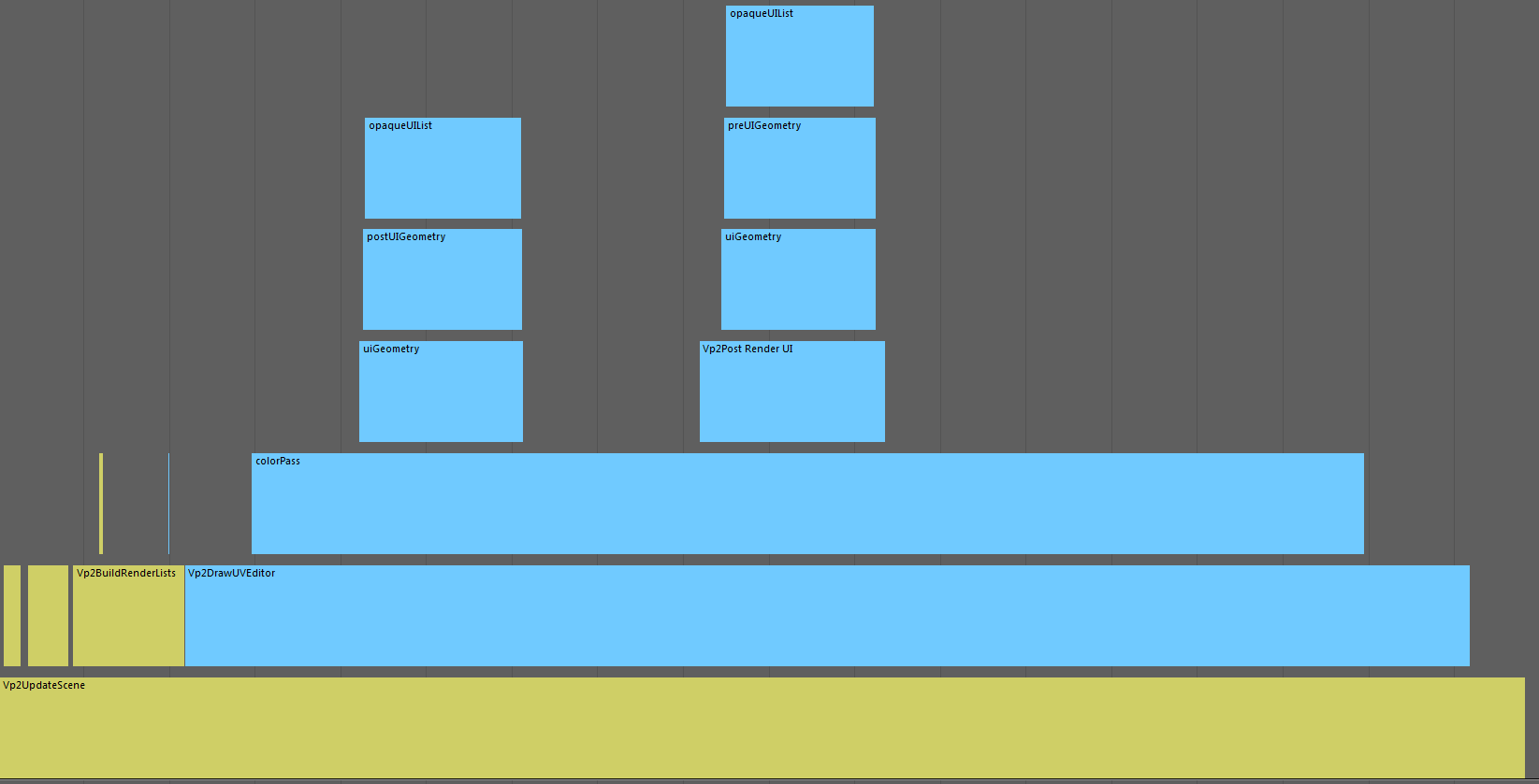
The following graph illustrates events for the background, as well as the UI rendered on top (Vp2Post Render UI). Vp2Post Render UI is an example of an event label of the form Vp2<ui list name>.
When a manipulator is used to perform UV component transformation, additional UI events are added. Vp2Manipulator is another example of an event label of the form Vp2<ui list name>.
