Deformers in the Dependency Graph
Deformers are placed in the construction history of a shape that is being deformed. The following figure shows a typical dependency graph including the deformers.

The deformed shape node (pSphereShape) is shown on the right of the dependency graph. The intermediate object (pSphereShapeOrig) is shown on the left of the dependency graph. The intermediate object is at the head of each chain of deformers, but is not displayed until you disable its intermediateObject attribute. The intermediate object acts as storage for the original undeformed positions of the shape.
In a typical deformer chain, shape data flows out of the intermediate object and then flows through each of the deformers. In this example, the deformers that are traversed are highlighted in yellow: tweak1, cluster1, and ffd1. Only a single shape flows through ffd1. However, most deformers can operate on any number of shapes because the input and output geometry attributes of the deformer base class are multis. The two exceptions to this rule are the skinClusters and wrap node, which can operate on only a single geometry. Additional geometries connected to the skinCluster and wrap node are ignored.
The dotted lines in the dependency graph indicate that some auxiliary nodes are not displayed. In this example, the auxiliary nodes are the groupParts nodes, which are used to store component lists for the deformer sets.
Deformers and Sets
Each deformer is associated with a single set. It only deforms the points that are included in the associated set. If you add points to a set using the sets command, the deformer is automatically associated with the construction history of the shape. Similarly, if you remove the points from a set, the deformer stops acting on the removed points. The set used by the deformer is a vertex-restricted set that can only contain vertices. The easiest way to find the associated set of a deformer is using the MFnGeometryFilter::deformerSet method. The returned set can then be used for creating an MFnSet, which can be used to access the membership information. The following code snippet provides an example.
MFnGeometryFilter fnDeformer(defObject);
    MObject setObject = fnDeformer.deformerSet();
    MFnSet fnSet(setObject);
    MSelectionList members;
    fnSet.getMembers(members,false);
    MItSelectionList itr( members );
    for (; !itr.isDone(); itr.next()) {
        MDagPath path;
        MObject components;
        itr.getDagPath(path, components);
        …
    }
GroupParts Node and GroupId Node
Most sets in Maya consist of only the objectSet node. However, the component sets in Maya are stored within the shape data rather than within the objectSet node. The set is connected to a groupId node for each shape, and a groupParts node for each shape with construction history. By default, Maya hides the groupParts and the groupId nodes in the hypergraph because they clutter the view. You can turn on the display of auxiliary nodes to view the groupParts and groupId nodes. The following figure shows a hypergraph view of the groupParts, groupId, and objectSet nodes for an ffd deformer. The tweak nodes are deleted from the shape's history to make the hypergraph less cluttered.

The groupId node stores an ID that is unique in a scene for quickly determining the membership of the set within the shape's list of sets. The groupParts node stores the component sets for shapes with construction history. As the shape data flows through the history, it might change its numbering. Component lists are stored using the vertex index and some construction history nodes modify the vertex numbering, for example, polySplit and deleteComponent. The groupParts node is not affected by the vertex numbering changes because it is in the construction history. The groupPart node receives the shape data before the vertices are renumbered. This architecture is useful in certain poly-modeling operations. However, it can cause issues in the following scenarios:
- If you modify the construction history ahead of a groupParts node, your set might no longer contain reasonable indices.
- If you modify the topology after a groupParts node, it can become difficult to edit the earlier weights or other details in the dependency graph that rely on a different indexing scheme.
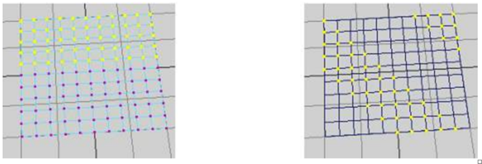
For example, consider that you have created a 10 x 10 polyPlane with history. You have selected the upper vertices in the plane, and then created a cluster. The cluster acts on the selected vertices, which are contained in its set. Now, you select the history node for the plane and modify the plane's number of divisions from 10 x 10 to 9 x 10. The membership of the cluster is now different than what you had originally specified. The following figure illustrates this example. The membership of the cluster that is created on a 10 x 10 plane is shown on the left and after the history is modified to 9 x 10 is shown on the right.

If you have spent significant time weighting vertices, this can be very inconvenient. To prevent this, you can follow a workaround, such as exporting the weight map before changing the topology, and then importing the weight map.
